Heat-conduction oil furnace of horizontal circulating fluidized bed

A circulating fluidized bed, heat transfer oil furnace technology, applied in fluidized bed combustion equipment, fluid heaters, heat storage heaters, etc., can solve the problems of high emission of air pollutants and low combustion efficiency, and reduce initial The effect of investment, high combustion efficiency and high desulfurization efficiency

Active Publication Date: 2013-12-04
BEIJING NOWVA ENERGY TECH CO LTD
View PDF8 Cites 14 Cited by
  • Summary
  • Abstract
  • Description
  • Claims
  • Application Information

AI Technical Summary

Problems solved by technology

[0004] In view of the deficiencies and defects of the existing technology, the purpose of the present invention is to propose a heat-conducting oil boiler using horizontal circulating fluidized bed technology, in order to solve the problem that the existing heat-conducting oil furnace can only burn high-quality bituminous coal, and the combustion efficiency is low. The problem of high pollutant emissions

Method used


Image

  • Heat-conduction oil furnace of horizontal circulating fluidized bed
  • Heat-conduction oil furnace of horizontal circulating fluidized bed
  • Heat-conduction oil furnace of horizontal circulating fluidized bed

Examples


Embodiment Construction

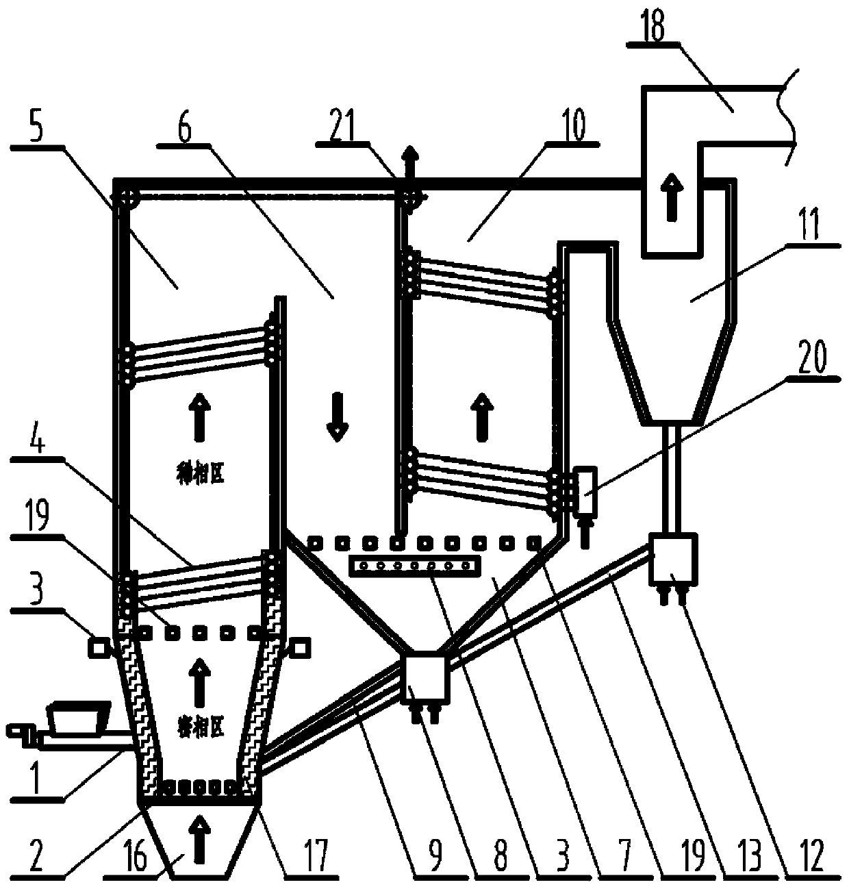
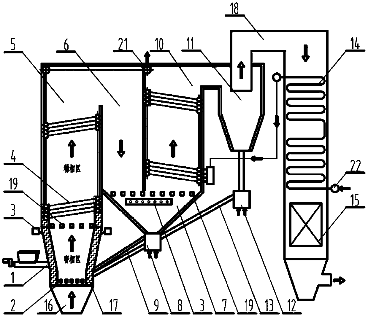
[0014] The specific embodiment of the present invention and working process will be further described below in conjunction with accompanying drawing.

[0015] figure 1 It is a schematic diagram of a horizontal circulating fluidized bed heat-conducting oil furnace according to the present invention, which includes a feeding device 1, a main combustion chamber 5, a secondary combustion chamber 6, a burnout chamber 10, a cyclone separator 11, a separator outlet flue 18 and An induced draft fan; the air distribution plate 2 is arranged at the lower part of the main combustion chamber 5, and the primary air device 16 is arranged at the lower end of the air distribution plate 2; the wear-resistant and refractory castable layer 17 is arranged in the dense phase area of ​​the main combustion chamber 5; 10 is arranged below the ash hopper 7, and the first-stage return device 8 is arranged below the ash hopper 7; the second-stage return device 12 is arranged under the cyclone separator ...


PUM


Abstract

The invention discloses a heat-conduction oil furnace of a horizontal circulating fluidized bed, and relaters to combustion equipment of the circulating fluidized bed for inferior coal, solid wastes, urban and industrial sludge and biomass fuels, in particular to a heat-conduction oil heating device. The heat-conduction oil furnace is mainly composed of a feeding device, a main combustion chamber, an auxiliary combustion chamber, an after-combustion chamber and a cyclone separator, wherein heat-conduction oil coils are arranged in the main combustion chamber and the after-combustion chamber, an economizer and an air pre-heater can be arranged behind the cyclone separator, and a waste heat boiler can also be arranged behind the cyclone separator. The heat-conduction oil heating device adopts a horizontal circulating fluidized bed technology, changes the traditional structural style adopting a chain grate furnace to heat, changes the single-stage and vertical circulating structure of the traditional fluidized bed boiler, effectively reduces the height of the boiler, and reduces the requirement on the construction height of plants. Through reasonable structural layout, the problem that the circulating fluidized bed boiler is easily abraded is effectively solved, and the heat-conduction oil heating device has wide adaptability to fuels, has high combustion efficiency, and has lower pollutant discharging quantity.

Description

technical field [0001] The invention relates to a heat-conducting oil furnace, in particular to a heat-conducting oil furnace adopting horizontal circulating fluidized bed technology. Background technique [0002] Heat-conducting oil furnace is a new type of special boiler with heat-transfer fluid as the heating medium, which has low-pressure and high-temperature working characteristics. Although the working pressure of the organic heat carrier furnace is relatively low, the temperature of the heat transfer fluid in the furnace is high, and most of them are flammable and explosive. Once leakage occurs during operation, it will cause fire, explosion and other accidents, and even cause casualties and property loss. Therefore, the general requirement for organic heat carrier furnaces is high energy efficiency under the premise of ensuring safety. Due to the wear and tear of the heating surface during the operation of circulating fluidized bed boilers in the past, circulating f...

Claims


Application Information

Patent Timeline
IPC IPC(8): F24H7/00F23C10/10F23C10/18
Inventor 康建斌王谦胡峰张哲李俊臣
Owner BEIJING NOWVA ENERGY TECH CO LTD
Why Eureka
Try Eureka