Impingement flow partially premixed low nitrogen gas burner

A gas burner and impinging flow technology, applied in the direction of gas fuel burners, burners, combustion types, etc., can solve the problems of thermal efficiency impact, rising CO emission concentration, low thermal efficiency, etc., and achieve strong fuel adaptability and pollutant emissions. Small, wide fuel adaptability effect

Active Publication Date: 2018-11-23
TSINGHUA UNIV +2
View PDF7 Cites 0 Cited by
  • Summary
  • Abstract
  • Description
  • Claims
  • Application Information

AI Technical Summary

Problems solved by technology

[0008] According to the development stage of low-nitrogen combustion industrial application technology, it can be roughly divided into three development stages: first, the use of staged combustion technology can control the NOx emission concentration at 100mg / m 3 , but this technology may cause a significant increase in the concentration of CO emissions; second, the use of flue gas recirculation technology can control the emission concentration of NOx at 60~80mg / m 3 According to the flue gas circulation ratio, the emission level varies greatly. This technology has a low cost and is suitable for renovation and upgrading, but it has no effect on the control of fast NOx and increases the power consumption of the fan; third, the premixed combustion technology , can control the emission concentration of NOx to 10~60mg / m 3 , can be adjusted within a certain range according to the requirements of environmental protection standards. This technology has a low cost and is suitable for new projects, but it has a slight impact on the overall thermal efficiency (about 1~2% in terms of low calorific value), that is, NOx emissions The lower the concentration, the lower the thermal efficiency, and there are also safety issues

Method used


Image

  • Impingement flow partially premixed low nitrogen gas burner
  • Impingement flow partially premixed low nitrogen gas burner
  • Impingement flow partially premixed low nitrogen gas burner

Examples


Embodiment Construction

[0022] The impinging flow partially premixed low-nitrogen gas burner provided by the present invention will be further described in detail below with reference to the accompanying drawings and specific embodiments.

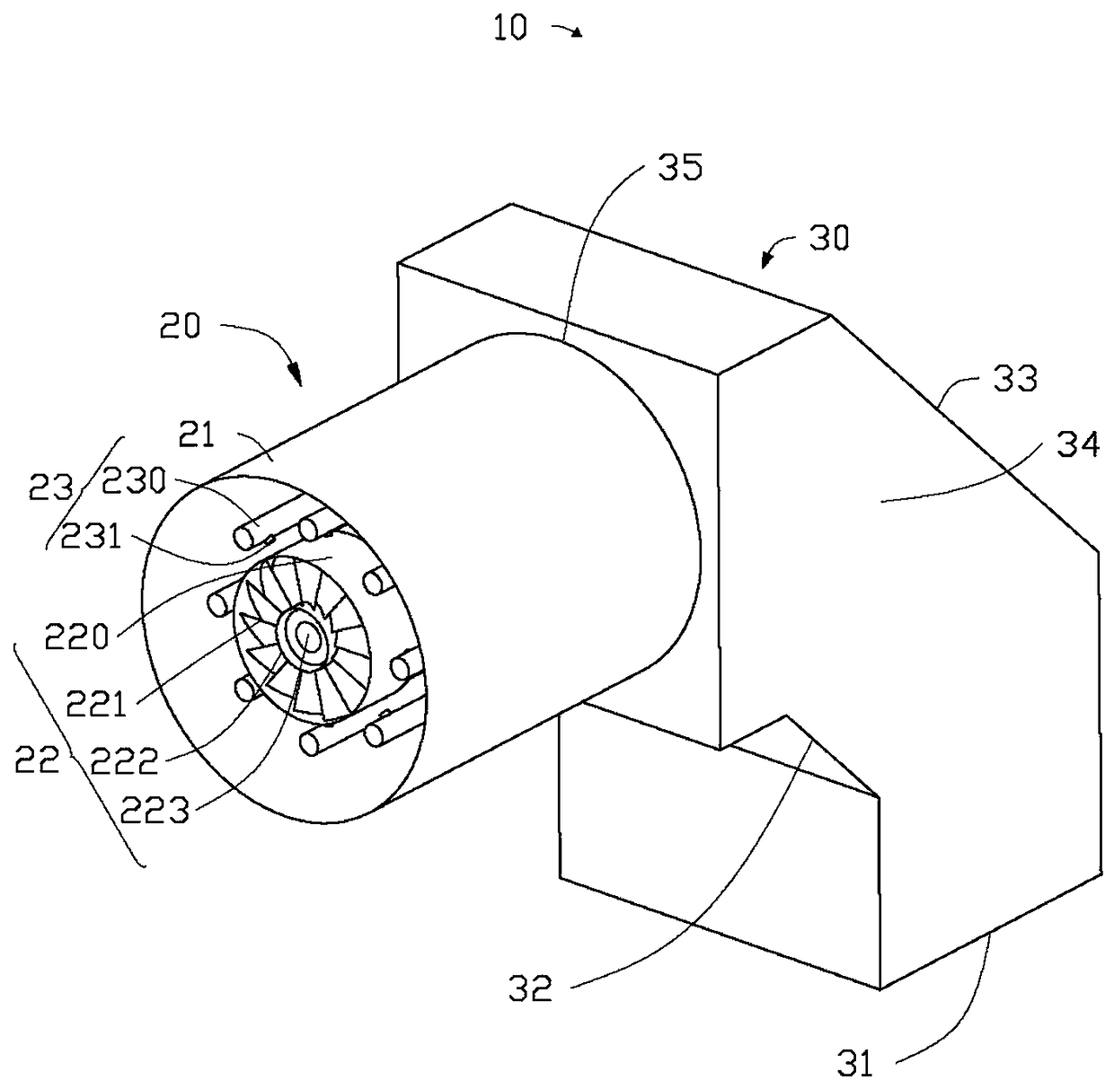
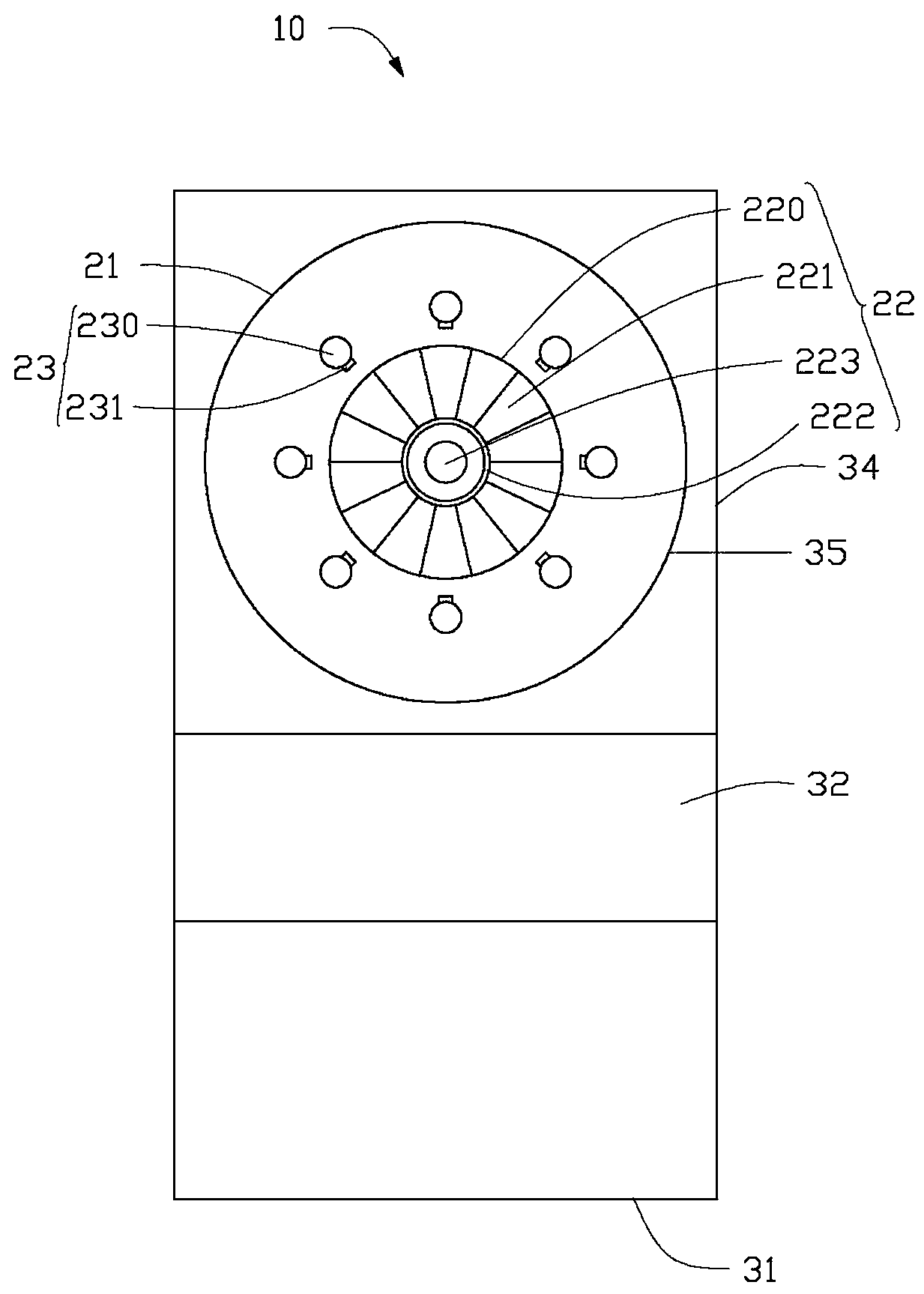
[0023] see figure 1 , the embodiment of the present invention provides an impingement flow partly premixed low nitrogen gas burner 10, the impingement flow part premixed low nitrogen gas burner 10 includes a combustion head 20 and a front flow channel 30, the combustion head 20 and the front flow channel The lanes 30 are connected together and communicate.

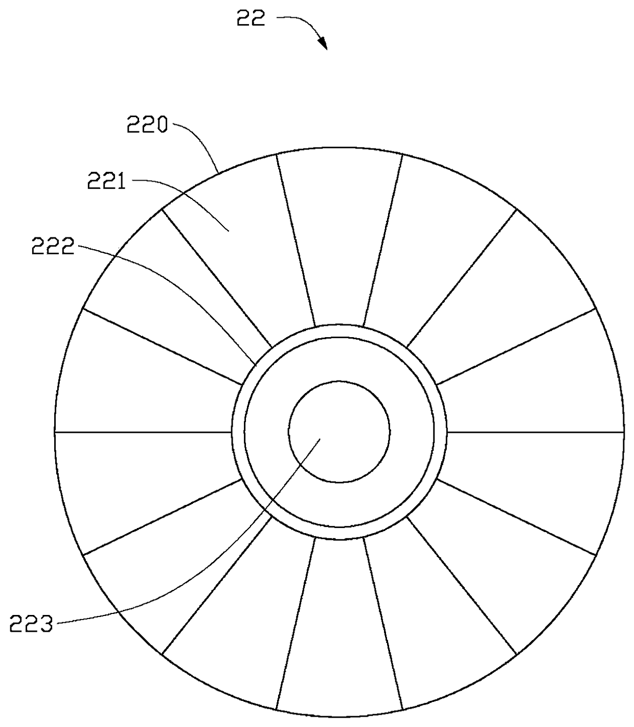
[0024] The combustion head 20 includes a cylindrical air flow passage 21, a swirler 22 arranged inside the cylindrical air flow passage 21, a fuel injector arranged outside the swirler 22 and inside the cylindrical air flow passage 21. Tube 23. The front flow passage 30 includes an air inlet 31, an air front deflector 32 and an air rear deflector 33 arranged behind the air inlet, an air inlet section 34 and ...


PUM


Abstract

The invention relates to an impinging stream part pre-mixing low-nitrogen gas combustor. The impinging stream part pre-mixing low-nitrogen gas combustor comprises a combustion head. The combustion head comprises a cylindrical air runner, a whirlcone arranged in the cylindrical air runner and fuel spraying pipes. The whirlcone comprises an outer ring, an inner ring, spinning disks arranged between the outer ring and the inner ring, and a center bluff body arranged in an inner center hole. The fuel spraying pipes are arranged on the outer side of the combustor whirlcone and located in the cylindrical air runner. Each fuel spraying pipe comprises a fuel pipe and a fuel spraying opening formed in the side face of the fuel pipe.

Description

technical field [0001] The invention relates to a low-nitrogen gas burner, in particular to a partly premixed low-nitrogen gas burner with impinging flow. Background technique [0002] Nitrogen oxide (NOx) is one of the main pollution sources of the atmosphere. It can not only form acid rain or acid fog, but also an important precursor of PM2.5 secondary particulate matter. As environmental pollution continues to intensify, smog and haze frequently appear in key areas of our country, which has caused great harm to people's health. With the combustion and utilization of natural gas, petroleum liquefied gas and coal synthesis gas, the pollution of gas combustion, especially the reduction of NOx emissions, is an urgent task. Therefore, it is of great significance to control the production of NOx during the combustion of natural gas. [0003] Combustion theory divides the formation of NOx into thermal NOx, rapid NOx and fuel NOx. The nitrogen content in natural gas is low, an...

Claims


Application Information

Patent Timeline
Patent Type & Authority Patents(China)
IPC IPC(8): F23D14/02F23D14/26F23D14/46F23D14/70
Inventor 卓建坤宋少鹏宋光武李娜姚强潘涛金大建冯复兴肖小华
Owner TSINGHUA UNIV
Why Eureka
Try Eureka