Mechanical arm for automatic blood type detector
An automatic detection and manipulator technology, applied in the field of medical equipment, can solve the problems of low utilization rate, complex structure, high cost, etc., and achieve the effect of reducing cost, simple mechanical structure, improving clamping reliability and service life
- Summary
- Abstract
- Description
- Claims
- Application Information
AI Technical Summary
Problems solved by technology
Method used
Image
Examples
Embodiment 1
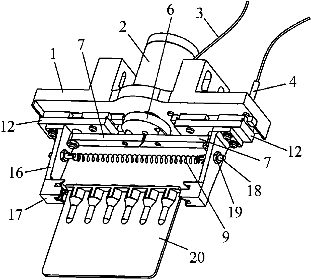
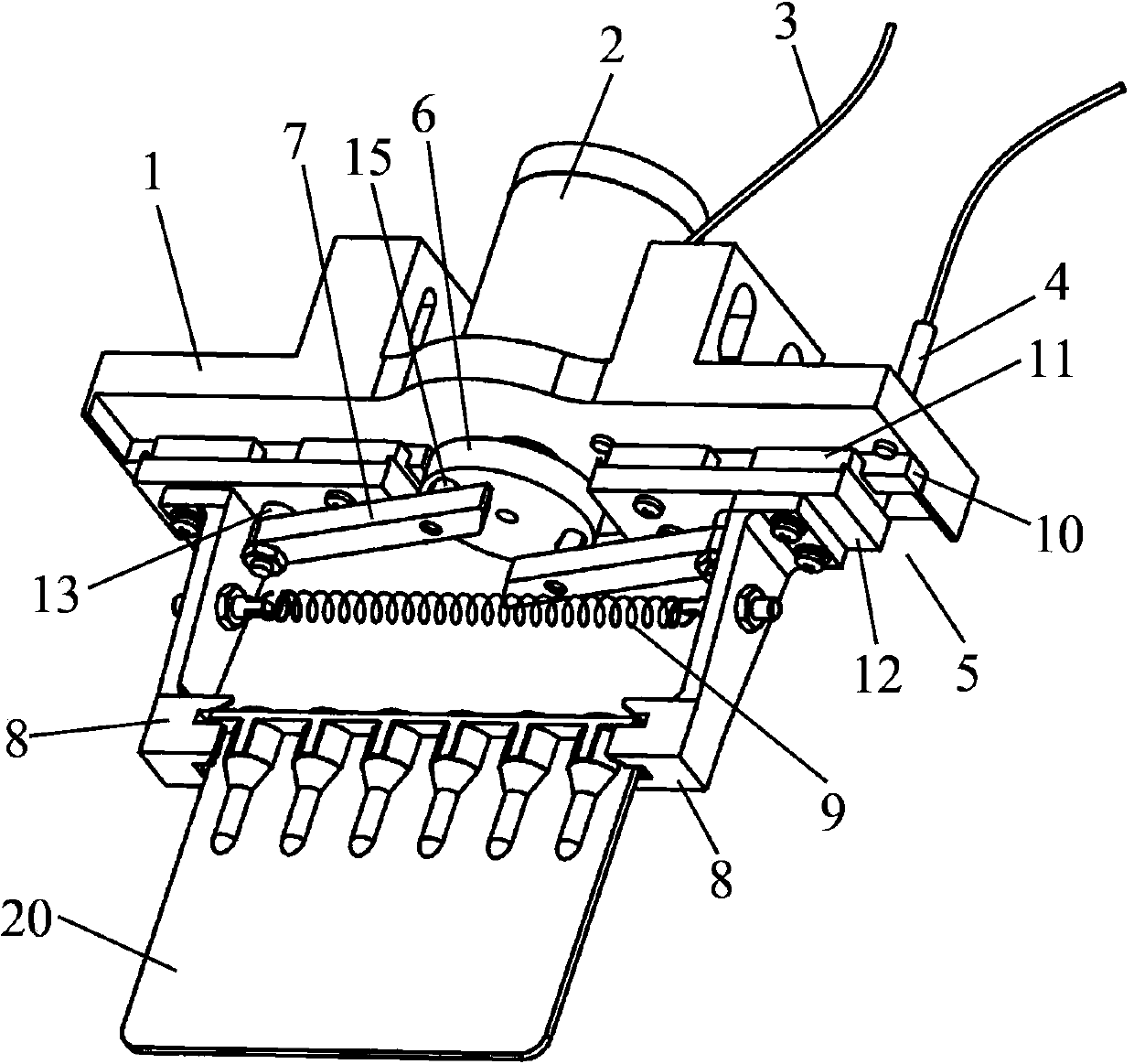
[0032] Such as Figure 1-Figure 4 As shown, a manipulator for an automatic blood type detector includes a support 1, a drive motor 2 installed on the support 1, a first sensor 3, a second sensor 4, two linear guide rail assemblies 5, and the drive motor 2 vertically supports The seat 1 is set, the drive motor 2 is fixed with a crank wheel 6, and the two linear guide rail assemblies 5 are respectively connected with the crank wheel 6 through the connecting rod 7, and each linear guide rail assembly 5 is fixed with a clamping piece 8, and the two clamping A tension spring 9 is connected between the parts 8, and the tension spring 9 is arranged parallel to the linear guide rail assembly 5.
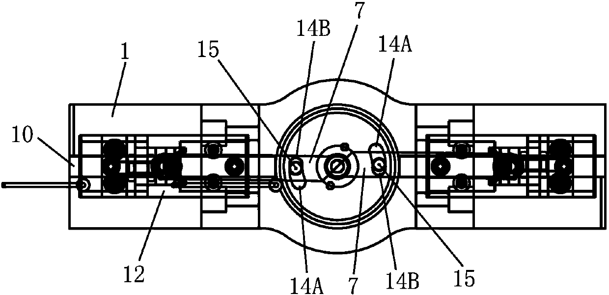
[0033] The preferred linear guide rail assembly 5 of the present invention includes a guide rail 10, a slider 11 sliding along the guide rail 10, and a connecting plate 12 fixed to the slider 11. The guide rail 10 is fixed on the support 1, and a positioning pin 13 is fixed on the connecting ...
Embodiment 2
[0041]Such as Figure 5-Figure 8 As shown, the difference between the second embodiment and the first embodiment is that the peripheral surface of the crank wheel 6 is provided with a boss 21, when the clamping head 17 moves to the closed state, that is, when the clamping head 17 clamps the blood card 20, the boss 21 The position of 21 is the first rotation position; when the clamping head 17 moves to the open state, that is, when the clamping head 17 releases the blood card 20, the position of the boss 21 is the second rotation position. One end of the first sensor 3 and one end of the second sensor 4 both vertically extend out of the support 1 , the first sensor 3 is set corresponding to the first rotation position, and the second sensor 4 is set corresponding to the second rotation position.
[0042] The working principle of this embodiment is as follows:
[0043] When the driving motor 2 rotates in the forward direction, the crank wheel 6 connected to the driving motor 2 ...
PUM
 Abstract
Description
Claims
Application Information
 - R&D
- Intellectual Property
- Life Sciences
- Materials
- Tech Scout
- Unparalleled Data Quality
- Higher Quality Content
- 60% Fewer Hallucinations
Browse by: Latest US Patents, China's latest patents, Technical Efficacy Thesaurus, Application Domain, Technology Topic, Popular Technical Reports.
© 2025 PatSnap. All rights reserved.Legal|Privacy policy|Modern Slavery Act Transparency Statement|Sitemap|About US| Contact US: help@patsnap.com


