
An electric cylinder tensile load and life test device

A life test device and life test technology, applied in the direction of measuring device, measuring electricity, measuring electrical variables, etc., can solve the problems of inability to achieve closed-loop control, inaccurate results, and complicated control, so as to increase work safety and improve test efficiency. , to ensure the effect of control accuracy

Active Publication Date: 2015-08-12
NO 771 INST OF NO 9 RES INST CHINA AEROSPACE SCI & TECH
View PDF3 Cites 0 Cited by
  • Summary
  • Abstract
  • Description
  • Claims
  • Application Information

AI Technical Summary

Problems solved by technology

Existing electric cylinder load test devices mainly use hydraulic cylinders to achieve special loading. Therefore, when conducting tests, not only can only one electric cylinder be tested and tested for load and life at a time, but additional special hydraulic cylinders are also required. As a loading device and an expensive hydraulic servo control system as a control servo
Therefore, the efficiency of the test is low, the cost is high, the control is complicated, and the closed-loop control cannot be realized. The accuracy will be affected by the hydraulic system itself, and the result is not accurate enough.

Method used


Image

  • An electric cylinder tensile load and life test device
  • An electric cylinder tensile load and life test device
  • An electric cylinder tensile load and life test device

Examples


Embodiment Construction

[0024] The present invention will be further described in detail below in conjunction with specific embodiments, which are explanations of the present invention rather than limitations.

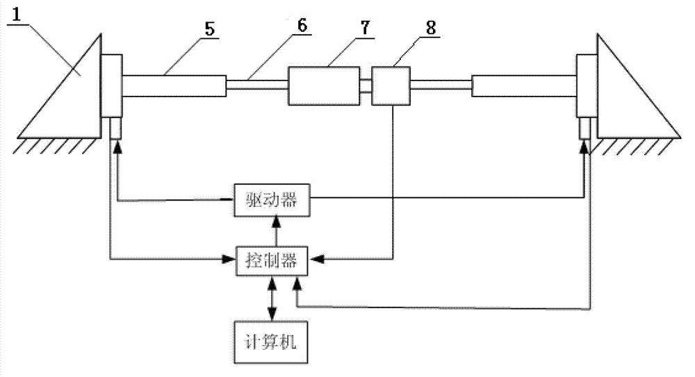
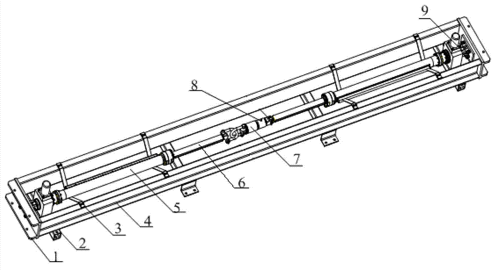
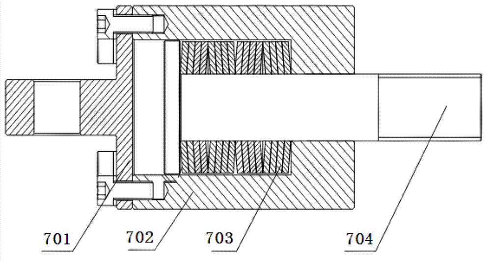
[0025] see figure 1 and figure 2 , the present invention includes a test bench 4 for supporting two electric cylinders 5, a connecting piece for connecting the drive rods 6 of the two electric cylinders 5, for fixing the two electric cylinders 5 respectively and keeping the two electric cylinders 5 at Auxiliary components in the same linear direction, and a control system for controlling the motor of the electric cylinder 5 and collecting the tension data or pressure data of the interaction between the two electric cylinders 5; Between the force sensor 8.

[0026] When carrying out the test, the electric cylinder 5 is respectively fixed on the test bench 4, and the force sensor 8 is connected with the free end joint of the drive rod 6 to complete the preparation for the test of the electri...


PUM


Abstract

The invention relates to an electric cylinder load and life test device which is high in test efficiency, convenient to use and high in adaptability. The electric cylinder load and life test device comprises a test bench, a connector, accessories and a control system, wherein the test bench is used for supporting two electric cylinders, the connector is used for connecting driving rods of the two electric cylinders, the accessories are used for respectively fixing the two electric cylinders and keeping the two electric cylinders in the same linear direction, and the control system is used for controlling motors of the electric cylinders and acquiring tension data or pressure data of interaction of the two electric cylinders. The control system comprises a force sensor, a driver, a controller and a computer, wherein the force sensor is connected between the two driving rods, the driver is used for directly controlling rotation of the motors, the controller is used for transmitting control commands to the driver and respectively acquiring information fed back by the force sensor and the motors, and the computer is used for transmitting the commands and extracting the data through the controller. When load and life tests are made, the two driving rods are the same in moving direction, and an elastic connecting device for buffering is arranged between the driving rods.

Description

technical field [0001] The invention relates to the field of tension load and life test of electric cylinders and other linear motion mechanisms, in particular to an electric cylinder tension load and life test device. Background technique [0002] Electric cylinder load and life assessment test is an important assessment index of electric cylinder products, and in the electric cylinder load and life assessment, the electric cylinder load life test device is the most important test and testing equipment. Existing electric cylinder load test devices mainly use hydraulic cylinders to achieve special loading. Therefore, when conducting tests, not only can only one electric cylinder be tested and tested for load and life at a time, but additional special hydraulic cylinders are also required. As a loading device and an expensive hydraulic servo control system as a control servo. Therefore, the efficiency of the test is low, the cost is high, the control is complicated, and the ...

Claims


Application Information

Patent Timeline
Patent Type & Authority Patents(China)
IPC IPC(8): G01R31/00
Inventor 魏浩东曲泓昺龚荣文李桐张强高巍
Owner NO 771 INST OF NO 9 RES INST CHINA AEROSPACE SCI & TECH
Learn More