Permanent-magnet torque adjuster

A regulator, permanent magnet technology, applied in electrical components, electromechanical devices, electromechanical transmission devices, etc., can solve the problems of complex maintenance and affect the service life of the motor, and achieve the effect of simple maintenance, lower investment costs, and savings in governance costs.

Active Publication Date: 2013-12-04
周庆根
View PDF6 Cites 3 Cited by
  • Summary
  • Abstract
  • Description
  • Claims
  • Application Information

AI Technical Summary

Problems solved by technology

[0007] 3. The use of a large number of electronic devices requires a special equipment operating environment and complex maintenance
[0008] 4. The load and the motor are hard-connected, and the vibration at the load end is directly transmitted to the motor, which affects the service life of the motor

Method used


Image

  • Permanent-magnet torque adjuster
  • Permanent-magnet torque adjuster
  • Permanent-magnet torque adjuster

Examples


Embodiment 1

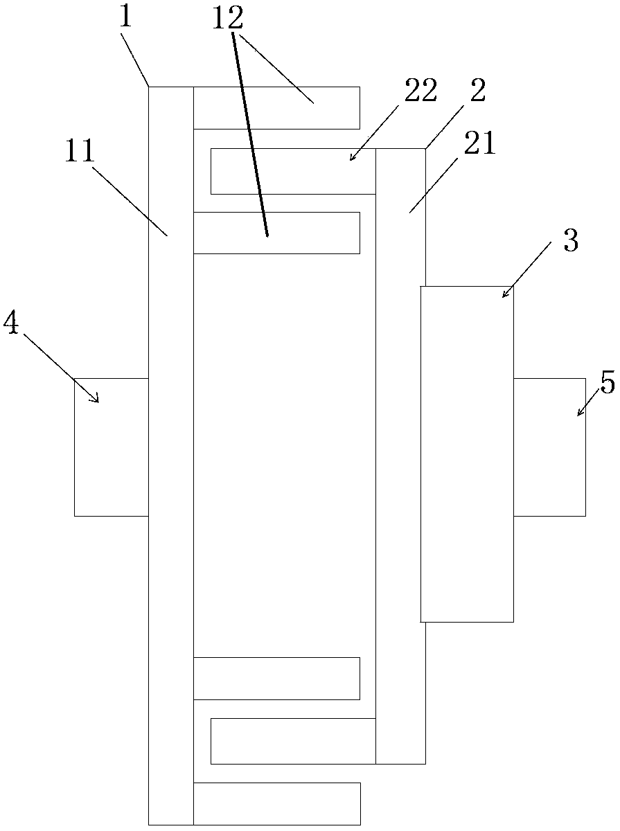
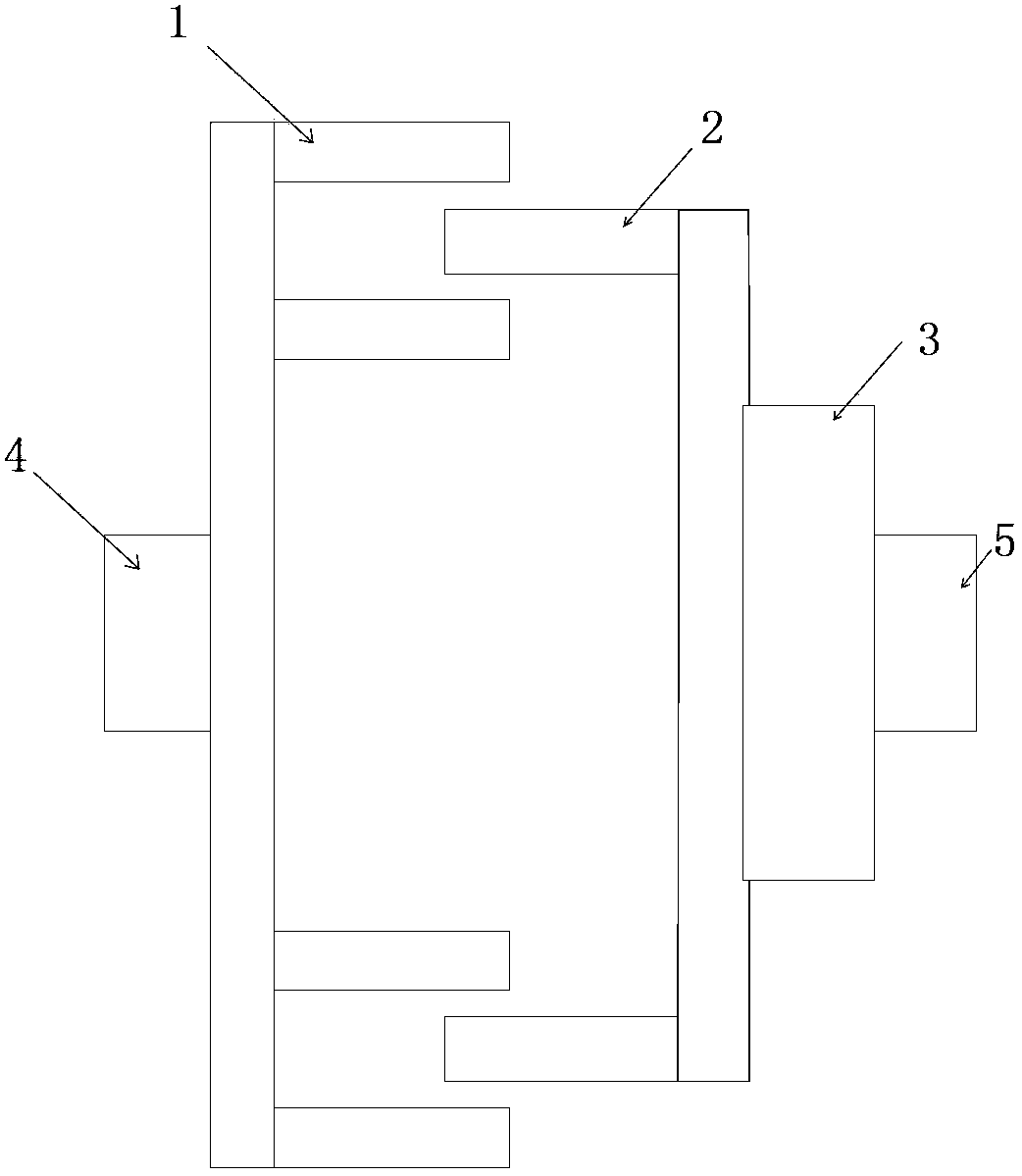
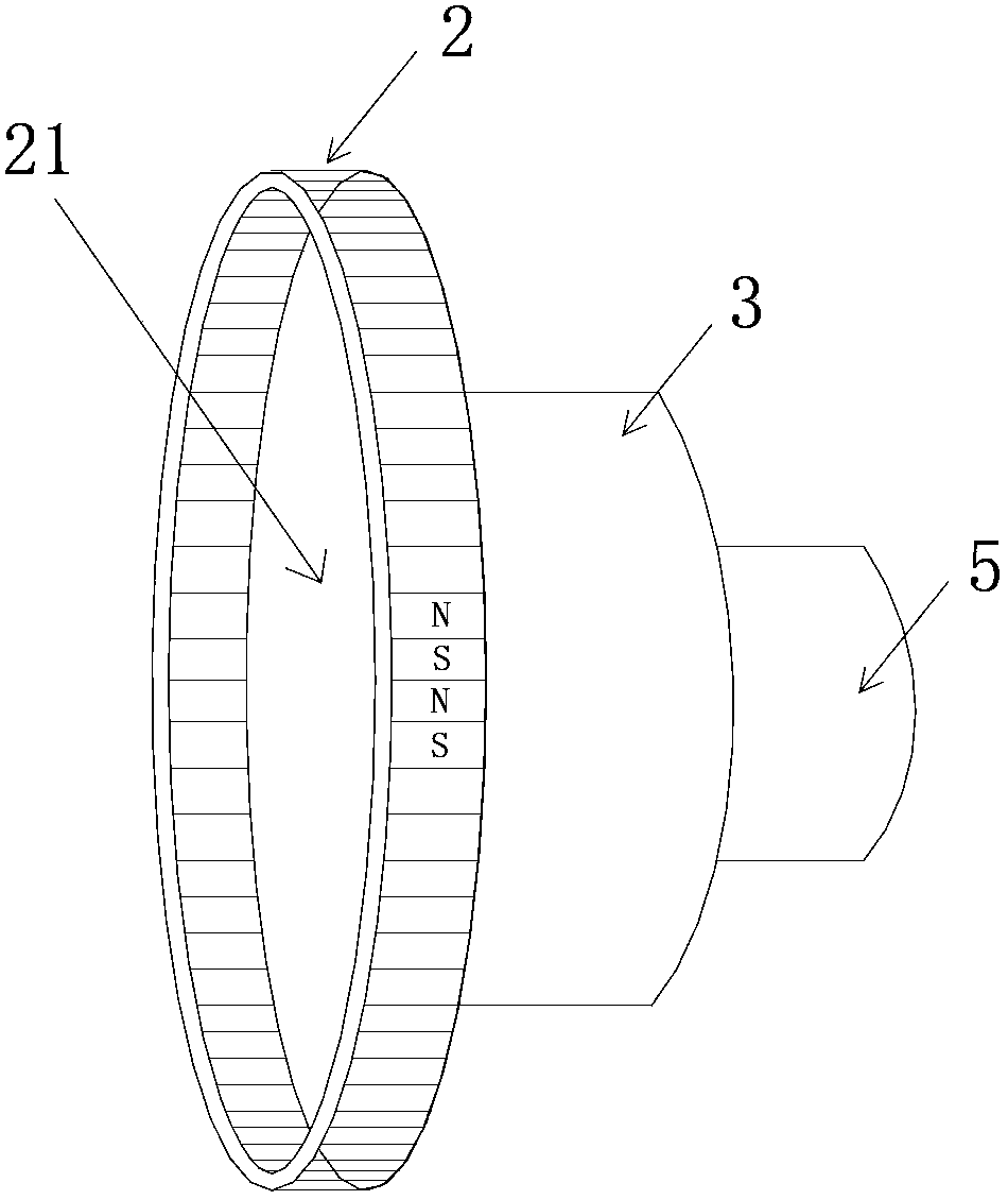
[0034] as attached figure 1 , 2 As shown, the permanent magnet torque regulator of the present embodiment is mainly composed of a conductor rotor 1 and a permanent magnet rotor 2; figure 1 , 4 As shown, the conductor rotor 1 includes a conductor support 11, and the conductor support 11 is provided with a conductor ring 12; as attached figure 1 , 3 As shown, the permanent magnet rotor 2 includes a fixed bracket 21, and the fixed bracket 21 is provided with a permanent magnet ring 22. The conductor ring 12 and the permanent magnet ring 22 are coupled without contact with each other, and the relative rotation realizes the magnetic field lines cutting.

[0035] Another example is attached figure 1 , 2 , 3, and 4, the conductor ring 12 of the conductor rotor 1 is an inner and outer layer, and the permanent magnet ring 22 of the permanent magnet rotor 2 is located between the inner and outer conductor rings 12, and it is connected to the inner and outer layers. The conductor ...

Embodiment 2

[0041] The difference between this embodiment and embodiment 1 is that, as attached figure 1 , 2 As shown in , 3, the conductor rotor 1 or the permanent magnet rotor 2 is provided with an adjustment device 3, and the adjustment device 3 is used to make the conductor rotor 1 or the permanent magnet rotor 2 generate axial displacement to increase or decrease the coupling area of ​​the two.

[0042] In this embodiment, the fixed bracket 21 of the permanent magnet rotor 2 is connected to the load shaft end 5 through the adjusting device 3 .

[0043] In the permanent magnet torque regulator of the present invention, the supporting ring of the conductor rotor 1 is made of non-ferromagnetic materials. The conductor ring is set on the support ring and fastened with fastening screws, and the outer support ring is connected with the outer support ring as a whole with connecting bolts.

[0044] The permanent magnet rotor 2 is organized by a fixed bracket and a permanent magnet block, t...


PUM


Abstract

The invention relates to the field of the transmission speed regulation technology, especially to a permanent-magnet torque adjuster. The permanent-magnet torque adjuster comprises a conductor rotator and a permanent-magnet rotor. The conductor rotor includes a conductor support; and a conductor ring is arranged at the conductor support. The permanent-magnet torque adjuster includes a fixed support; and a permanent magnet ring is arranged at the fixed support. And the conductor ring and the permanent magnet ring are coupled by a non-contact way; and magnetic lint cutting is realized by relative rotation. According to the invention, the torque is transmitted and adjusted by the non-contact way of the conductor and the permanent magnet, thereby achieving objectives of speed regulation and energy conservation.

Description

technical field [0001] The invention relates to the technical field of transmission speed regulation, in particular to a permanent magnet torque regulator. Background technique [0002] The speed regulation of mechanical transmission has experienced the development process of gear speed regulation, belt speed regulation, frequency conversion speed regulation and so on. The purpose of gear speed regulation and belt speed regulation is to achieve the purpose of speed regulation through different teeth numbers and diameters of the driving wheel and the driven wheel, mainly to meet the process requirements. Frequency conversion speed regulation is to achieve the purpose of energy saving by adjusting the frequency of the power supply and changing the speed of the motor. [0003] Frequency conversion speed regulation technology is a speed regulation and energy-saving technology widely used at present. Its main technology is to use high-power power electronic devices to rectify a...

Claims


Application Information

Patent Timeline
Patent Type & Authority Applications(China)
IPC IPC(8): H02K51/00
Inventor 周庆根柳志明
Owner 周庆根
Why Eureka
Try Eureka