Chemical carbon dioxide gas generator

A gas generator, carbon dioxide technology, applied in the field of applied chemistry, can solve problems such as unusable fire extinguishers, unsuitable gas, unfavorable oxygen reactivity, etc.

Active Publication Date: 2013-12-04
荷兰应用自然科技研究组织TNO
View PDF10 Cites 8 Cited by
  • Summary
  • Abstract
  • Description
  • Claims
  • Application Information

AI Technical Summary

Problems solved by technology

While this generator can be used as an alternative to nitrogen in some applications, the reactivity of oxygen can be unfavorable or make the gas produced unsuitable for a particular purpose
Generally, the gas cannot be used in fire extinguisher applications and may contribute to oxidation reactions such as corrosion of materials in contact with oxygen

Method used


Image

  • Chemical carbon dioxide gas generator
  • Chemical carbon dioxide gas generator
  • Chemical carbon dioxide gas generator

Examples


preparation example Construction

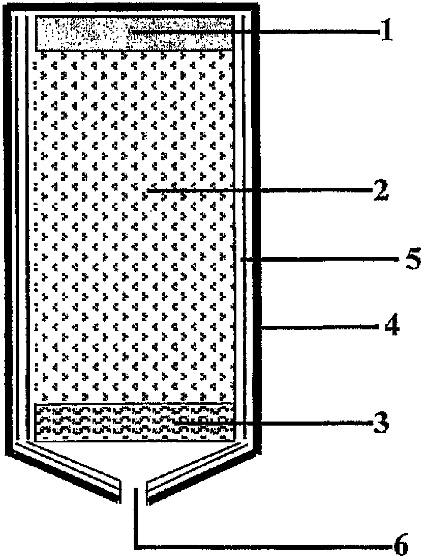
[0055] The preparation of charges with suitable properties may be based on methods known per se, for example based on the methods described in WO03 / 009899 or WO01 / 23327, combined with the information disclosed herein, common general knowledge and optionally some routine testing.

[0056] As mentioned above, the charge is permeable to the gas produced. Advantageously, therefore, the charge is of such a structure that channels (openings) are contained in the structure. Such a structure may in particular be provided by granular material in which the particles are bound together (by means of a binder). The gas can pass through the interstices between the particles, and / or - if the particles are porous - through the pores in the particles. Usually, the porosity (ε p ) in the range of 0.2-0.75. For good gas flow performance, good material strength and good CO 2 Productivity, preferably, the porosity is in the range of 0.30-0.65. In particular, the porosity (ε p Good results ha...

Embodiment

[0097] A charge consisting of magnesium carbonate, oxidizer, fuel and binder was prepared as follows: the dry powder was weighed and mixed thoroughly. Add the water soluble binder with the required amount of moisture and mix well again to get a homogeneous mixture. The mixture is then granulated, sieved, and placed into molds where it is compacted in several steps to the desired total porosity. The mold loaded with the wet porous charge was dried in an oven at a temperature range between room temperature and 150° C. according to an optimized drying profile. The charge is then removed from the mold and inspected visually.

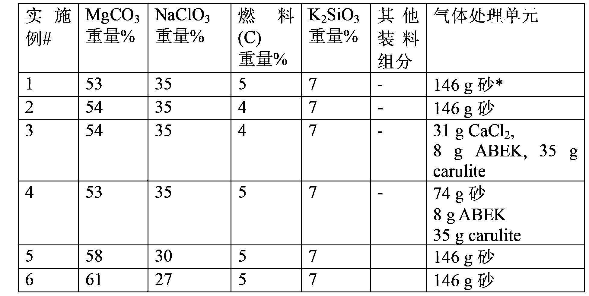
[0098] In the table below, the composition of the tested charge is given, as well as the gas treatment unit used (downstream of the charge in the gas generator). The total weight of the charge is about 100 g.

[0099]

[0100] *) Note: When using only sand, the amount used is not optimal. The amount used is that required to fill the free space in the ...


PUM

PropertyMeasurementUnit
diameteraaaaaaaaaa
lengthaaaaaaaaaa
porosityaaaaaaaaaa

Abstract

A chemical carbon dioxide gas generator comprising: - a charge housing; - a carbon dioxide gas penetrable charge, contained in the said housing, the charge comprising a) 40-60 wt. % of a substance which upon decomposition generates carbon dioxide, which substance is selected from the group of magnesium carbonate, other carbonates, magnesium oxalate and other oxalates, b) 20-50 wt. % of an oxidiser selected from the group of sodium chlorate, potassium chlorate, lithium chlorate, other metal chlorates, sodium perchlorate, potassium perchlorate, lithium perchlorate, and other metal perchlorates, c) 1-20 wt. % of carbon or another fuel, d) 1-10 wt. % binder, said components a), b), c) and d) together forming 90-100 wt. % of the total weight of the charge; - an ignition device for igniting the charge; - a carbon dioxide gas treatment unit for reducing the content of one or more side-products - which may have been formed by the charge - in the generated carbon dioxide, and / or for cooling carbon dioxide gas generated by the charge; and - an outlet for carbon dioxide gas generated by the charge.

Description

technical field [0001] The present invention relates to applied chemistry, and more particularly to a chemical carbon dioxide gas generator, a device containing a chemical carbon dioxide gas generator, a method for generating carbon dioxide, and a charge suitable for generating carbon dioxide gas material). Background technique [0002] Methods of gas generation using chemical propellant-based decomposition or combustion are commonly used for many purposes, for example, for the inflation of inflatable devices such as air bags, lifeboats or lifejackets, for operating pneumatic devices, or in fire-extinguishing devices . [0003] Known chemical methods for obtaining relatively cool gases are generally based on the decomposition or combustion of solid materials in specialized units. These materials are usually in the form of solid block materials or as (loose) filled powders, loose granules or loose tablets. The hot gases produced by the decomposition of these materials are ...

Claims


Application Information

Patent Timeline
Patent Type & Authority Applications(China)
IPC IPC(8): C06B23/04C06D5/06C01B32/50
CPCB01J7/00C06B23/04C01B31/20C06D5/06C01B32/50
Inventor 劳伦斯·达尼埃尔·范·弗利特维奥拉·范·普尔·弗尔博姆科内利斯·安东尼厄斯·胡贝尔特斯·斯克玉比尔斯
Owner 荷兰应用自然科技研究组织TNO
Why Eureka
Try Eureka