Defoaming machine

A defoaming machine and defoaming technology, used in ceramic molding machines, manufacturing tools, etc., can solve the problems of poor quality, waste, and hollowing of foamed cement, saving installation space, improving production efficiency, and reducing process costs. Effect

Active Publication Date: 2013-12-11
CUBIC DIGITAL TECH CO LTD
View PDF6 Cites 1 Cited by
  • Summary
  • Abstract
  • Description
  • Claims
  • Application Information

AI Technical Summary

Problems solved by technology

Although the existing treatment method can achieve the purpose of increasing the pressure bearing capacity of the foamed cement surface, the disadvantages are obvious: first, a part of the foam needs to be cut off, which will inevitably generate a lot of waste and cause waste; secondly, the foamed cement and the above The curing time of the cement slurry containing the glass fiber net in the first layer is inconsistent, which is prone to hollowing, resulting in poor quality of the finished foamed cement and a high defective rate

Method used


Image

  • Defoaming machine
  • Defoaming machine
  • Defoaming machine

Examples


Embodiment 1

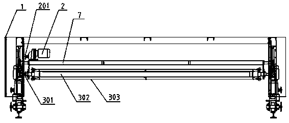
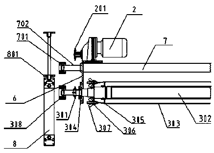
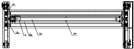
[0055] like Figure 1-2 As shown, the defoaming machine of this embodiment includes a frame 1, on which a support plate 7 is horizontally fixed, on which a drive motor 2 is installed, and two ends of the support plate 7 are respectively fixed with The connecting steel plate 6 is equipped with a main shaft 302, and the outer surface of the main shaft 302 is evenly arranged with defoaming parts along the circumferential direction; the defoaming machine of this embodiment also includes a transmission assembly, which is connected to the drive motor 2 and the main shaft 302, It is used to transmit the driving force of the driving motor 2 to the main shaft 302 to drive the main shaft 302 to rotate. The above-mentioned support plate 7, drive motor 2, connecting steel plate 6 and transmission assembly together constitute the defoaming assembly of the defoaming machine. When the driving motor 2 is working, the main shaft 302 rotates under the action of the transmission assembly, which...

Embodiment 2

[0077] This embodiment is a modification on the basis of Embodiment 1, and its difference from Embodiment 1 is that the limiting track is a highly undulating limiting track, and when the limiting wheel 901 walks on the limiting track, Its height is constantly changing, so that the height of the main shaft 302 and the steel wire 303 on the main shaft 302 relative to the body to be defoamed is constantly changing, so that this kind of defoaming machine can be used to have a non-horizontal upper surface to prepare the upper part with a specific thickness. Foamed cement for air-bubble cleaning layer.

[0078] Specifically, set limit rails with target height undulations on both sides of the object to be defoamed, adjust the horizontal upper surface of the object to be defoamed to match the highest track position, and adjust the defoamer to the position to be defoamed by the lifting device Above the body, adjust the relative height relationship between the limit wheel 901, the limit...

Embodiment 3

[0080] like Figure 12 As shown, this embodiment is a deformation on the basis of embodiment 1 or embodiment 2, the difference is that the above-mentioned defoaming member does not use steel wire, but by setting angle steel 309 on the defoaming main shaft, and connecting nylon on the angle steel 309 The ribbon 310 and the defoaming spindle 302 drive the nylon ribbon 310 to rotate, and then perform defoaming treatment on the defoaming layer of the defoaming body.


PUM


Abstract

The invention provides a defoaming machine. The defoaming machine comprises a frame, wherein the frame is horizontally provided with a supporting plate, the two ends of the supporting plate are fixedly connected with connection steel plates, and the lower parts of the connection steel plates are fixedly connected with bearings arranged on a main shaft; one end of the supporting plate is fixedly provided with a main shaft driving motor; the main shaft can rotate in the bearings, and the surface of the outer side of the main shaft is uniformly provided with defoaming components; the main shaft driving motor drives the main shaft to rotate. The defoaming machine disclosed by the invention directly removes air bubbles in surface foaming bodies of foam cement, so that the surface foaming bodies become a net slurry layer and can be subjected to composite connection with core materials so as to have very high strength; the waste caused by cutting off the surface foaming bodies in the prior art is avoided, and the surface foaming bodies after becoming the net slurry layer can be synchronously solidified with the below foam cement so that a hollowing situation is unlikely to generate; the processes of cutting off the surface foaming bodies, smearing cement slurry with fiberglass net and the like, are avoided, so that the technical process can be reduced, and the production efficiency is improved.

Description

technical field [0001] The invention relates to a defoamer capable of eliminating air bubbles on the surface of foamed cement. Background technique [0002] Foamed cement is a commonly used inorganic wall insulation material at present. It has low thermal conductivity, good insulation effect, heat resistance and fire prevention, sound insulation and waterproof, strong adhesion to the wall, non-toxic and radioactive substances, and is green and environmentally friendly. It can be in the same period as the service life of the building, and the construction is simple and fast, and its technical performance is better than that of phenolic foam board, polystyrene particles, polystyrene board, extruded board and other wall insulation materials. [0003] When foamed cement is used as a material for heat preservation or other functions, it usually needs to withstand a certain amount of pressure, and the foamed cement itself contains rich pores and cannot form an effective load-beari...

Claims


Application Information

Patent Timeline
Patent Type & Authority Applications(China)
IPC IPC(8): B28B11/00
Inventor 樊立
Owner CUBIC DIGITAL TECH CO LTD
Why Eureka
Try Eureka