Cooler descaling device

A cooler and high-pressure chamber technology, which is applied in the field of descaling devices for removing dirt on the inner wall of the cooler, to achieve the effects of saving descaling costs, high efficiency, and simple operation

Inactive Publication Date: 2013-12-11
山西新泰钢铁有限公司
View PDF3 Cites 9 Cited by
  • Summary
  • Abstract
  • Description
  • Claims
  • Application Information

AI Technical Summary

Problems solved by technology

[0002]At present, most of the coolers used in metallurgy and chemical industry in my country are cooled by conventional industrial water. Scaling of cooling walls and water pipes is inevitable. The resistance increases, causing the cooling wall to overheat and crack, peel off, and then block the cooling pipeline, etc., which greatly shortens the life of the cooler and also threatens the safe production of the equipment.
[0003]The common way to maintain the cooler is to regularly wash it with hydrochloric acid circulation chemical method. In addition to consuming a large amount of hydrochloric acid, this method also needs to heat the circulating cleaning solution. Long cleaning time, high cost, complicated operation, and high labor intensity make workers harmed by acid mist and cause serious environmental pollution
In addition, the scaling conditions of cooling water pipes are different in different parts. When using the existing technology to clean, only the same concentration of hydrochloric acid can be used for treatment. The parts with less scale should also be pickled for the same long time. It often happens that some parts are not completely descaled, and some parts are deeply corroded. lifespan decreases

Method used


Image

  • Cooler descaling device

Examples


Embodiment Construction

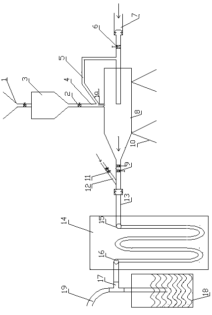
[0015] refer to figure 1 , a cooler descaling device of the present invention, the application on the cooler 14 of the blast furnace. The starting end of the device is a high-pressure gas source such as a high-pressure air pump (compressor) or other devices that generate high-pressure gas. A high-pressure chamber 8 is fixed on the bracket 10. The high-pressure gas source communicates with the high-pressure chamber 8 through a high-pressure valve 6 and a high-pressure intake pipe 7. , a pellet silo 3 is arranged on the upper part of the high-pressure chamber, and the pellet silo is communicated with the high-pressure chamber through a vertical discharge pipe 4, and a discharge valve 2 is arranged on the discharge pipe. There is also a receiving hopper 1 at the top of the pellet silo 3 . A high-pressure branch pipe 5 is connected to the high-pressure air inlet pipe 7, and the other port of the high-pressure branch pipe is connected with the blanking pipe 4 in a down-tilt state...


PUM


Abstract

The invention relates to a cooler descaling device, which comprises a high pressure air pump and a high pressure air inlet pipe, wherein the high pressure air inlet pipe is connected with the high pressure air pump, an outlet of the high pressure air pipe is arranged in a high pressure cavity, the upper part of the high pressure cavity is provided with a particle material bin, the particle material bin is communicated with the high pressure cavity through a vertical material falling pipe, a high pressure branch pipe is further arranged between the high pressure air inlet pipe and the material falling pipe, the high pressure branch pipe and the material falling pipe are connected in a downward inclining way, and the front end port of the high pressure cavity is connected with a water inlet of a cooler. The cooler descaling device has the advantages that particle materials are converted into high-energy physical kinetic energy by a high pressure spray nozzle of compressed air, and then a metal surface is treated; a cooling wall and a water pipe are cleaned by the technique, water scale can be removed, and the toughness of the cooling wall and that of a pipeline are reduced, so the heat transfer condition of the cooling wall is improved, the drag loss is reduced, and the service life of the cooling wall is prolonged; the method can replace a traditional acid cleaning method, the equipment structure is simple, the efficiency is high, the cost is low, and the pollution is avoided.

Description

Technical field: [0001] The invention relates to a descaling device, in particular to a descaling device for removing dirt on the inner wall of a cooler. It is suitable for cleaning the internal surface attachments (oxides, scale, grease, sediment, corrosion, etc.) of metal pipes such as cooling pipe walls and water pipe inner walls, and is widely used in metallurgy and chemical industries. Background technique: [0002] At present, most of the coolers used in metallurgy and chemical industry in my country are cooled by conventional industrial water. Scaling of the cooling wall and water pipes is inevitable. After the scaling of the pipe wall, the thermal resistance increases, causing the cooling wall to overheat and crack, peel off, and then block. Cooling pipelines, etc., greatly shorten the life of the cooler, and also threaten the safe production of the equipment. [0003] The common way to maintain the cooler is to regularly wash it with hydrochloric acid circulation ...

Claims


Application Information

Patent Timeline
Patent Type & Authority Applications(China)
IPC IPC(8): F28G1/12
Inventor 丁毅兰建云
Owner 山西新泰钢铁有限公司
Why Eureka
Try Eureka