Waveguide inflator

An inflator and waveguide technology, which is applied in the direction of electrical components, antennas, circuits, etc., can solve the problems of large air humidity difference and inconvenience of waveguide inflators, etc., and achieve the effect of simple structure, good use effect and low cost

Active Publication Date: 2015-07-15
XIAN JIAODA KAIDA NEW TECH
View PDF8 Cites 0 Cited by
  • Summary
  • Abstract
  • Description
  • Claims
  • Application Information

AI Technical Summary

Problems solved by technology

[0003] Most of the current waveguide inflators need to replace the desiccant (canister). When the waveguide inflator works for a period of time, the desiccant changes color and loses its drying effect. It must be replaced regularly to ensure the drying effect of the waveguide inflator on the air. However, it is necessary to replace the drying cylinder It needs to be manually operated, and because the humidity of the air in different areas varies greatly, the replacement cycle is also different, which brings great inconvenience to the actual use of the waveguide inflator

Method used


Image

  • Waveguide inflator
  • Waveguide inflator
  • Waveguide inflator

Examples


Embodiment 1

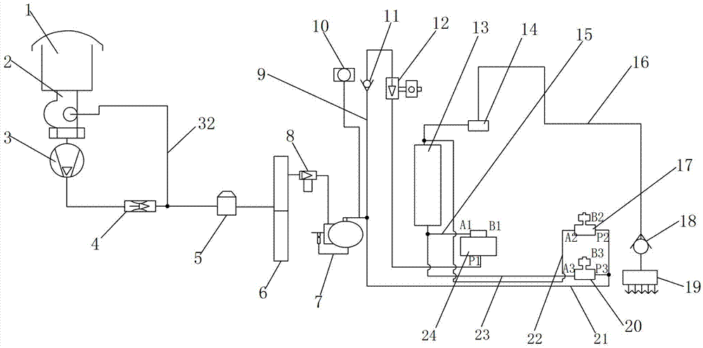
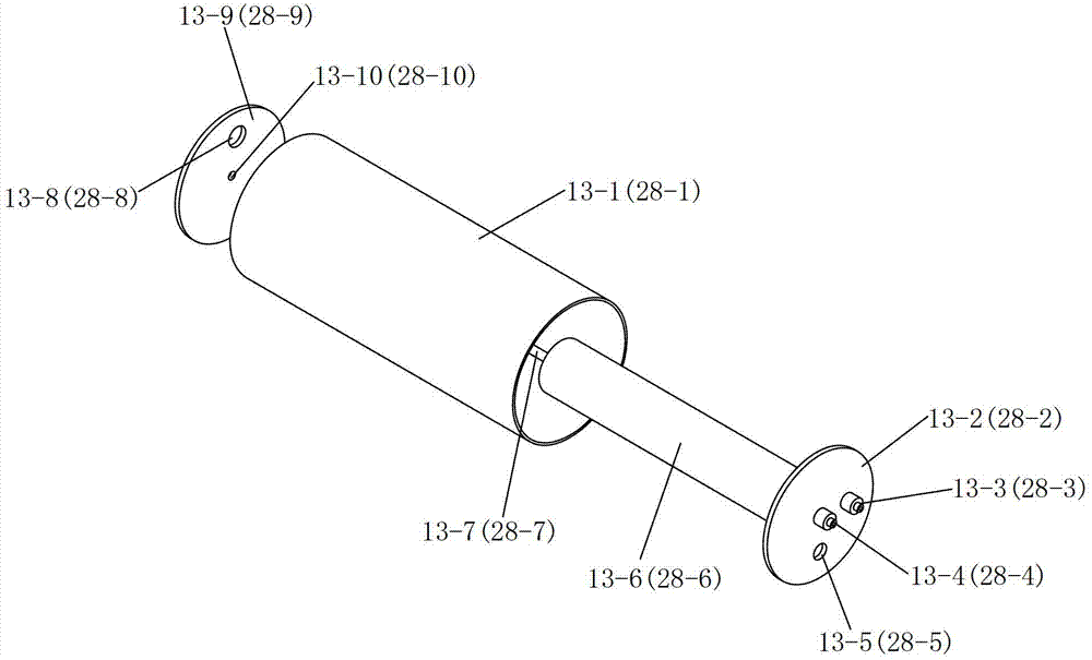
[0031] Such as figure 1 and image 3 The shown waveguide inflator includes an air intake valve 2, an air compressor 3, a first drying cylinder 13, and a first reversing valve 24, a second reversing valve 17 and a third reversing valve, all of which are two-position reversing valves. Reversing valve 20; the first drying cylinder 13 is filled with air desiccant, the first drying cylinder 13 is provided with a first heater 13-6, and one end of the first drying cylinder 13 is provided with a first Gas input port 13-5, the other end of the first drying cylinder 13 is provided with a first gas output port 13-8; the inlet valve 2 is connected to the input port of the air compressor 3, and the air compressor 3 The output port of the first reversing valve 24 is connected to the first gas port P1 of the first reversing valve 24 through the first gas delivery pipe 9, and the second gas port A1 of the first reversing valve 24 is connected to the first gas input port 13- 5 connection, th...

Embodiment 2

[0038] Such as image 3 and Figure 4 As shown, the only difference between this embodiment and Embodiment 1 is: the waveguide inflator also includes a second drying cylinder 28, the second drying cylinder 28 is filled with air desiccant, and the second drying cylinder 28 A second heater 28-6 is arranged inside, one end of the second drying cylinder 28 is provided with a second gas input port 28-5, and the other end of the second drying cylinder 28 is provided with a second gas output port 28- 8; The third gas port B1 of the first reversing valve 24 is connected with the second gas input port 28-5 through the seventh gas delivery pipe 31, the third gas delivery pipe 16 is connected with a shuttle valve 25, the second The gas output port 28-8 is connected to the shuttle valve 25 through the eighth gas delivery pipe 26, the first gas port P3 of the third reversing valve 20 is connected to the fourth gas delivery pipe 21, and the third reversing valve 20 The second gas port A3 ...


PUM


Abstract

The invention discloses a waveguide inflator. The waveguide inflator comprises an air inlet valve, an air compressor and a fist drying cylinder; a first heater is arranged in the first drying cylinder, a first air inlet is formed in one end of the first drying cylinder, and a first air outlet is formed in the other end of the first drying cylinder; an air output of the air compressor is connected with a first air port P1 of a first directional valve through a first air conveying pipe, a second air port A1 of the first directional valve is connected with the first air inlet through a second air conveying pipe, the first air outlet is connected with a third air conveying pipe, the first air conveying pipe is connected with a fourth air conveying pipe which is connected with a first air port P2 of a second directional valve, a second air port A2 of the second directional valve is connected with the first air outlet through a fifth air conveying pipe, the first air inlet is connected with a second air port A3 of a third directional valve through a sixth air conveying pipe, and a third air port B3 of the third directional valve is communicated with outside atmosphere. Under the circumstance that drying cylinders do not need to be dismounted, the waveguide inflator achieves dehumidification of air drying agents.

Description

technical field [0001] The invention belongs to the technical field of air drying, and in particular relates to a waveguide inflator. Background technique [0002] The waveguide drying and pressurizing equipment is collectively called the waveguide inflator. Its main function is to inflate the antenna feeder system to maintain a certain pressure of dry air in the feeder system, to ensure that external moist air and moisture cannot enter, and to prevent excessive reflected power due to feeder rust. Large and other practical problems of electrical performance degradation or damage to the transmission feeder, to ensure the normal operation of the communication system, it is an important supporting equipment for the communication system. Waveguide inflators are widely used in radio and television, electric power, communications, oil fields, water conservancy, waterway transportation, meteorology, aviation, geology, military and other departments of microwave stations, radio and ...

Claims


Application Information

Patent Timeline
Patent Type & Authority Patents(China)
IPC IPC(8): H01Q1/00B01D53/26
Inventor 庄严林俊亭郭钊王文攀张喜荣张小燕
Owner XIAN JIAODA KAIDA NEW TECH
Why Eureka
Try Eureka