Method for setting up reactive power compensation device model based on controlled alternating current source

A compensation device, AC current technology, applied in reactive power adjustment/elimination/compensation, flexible AC transmission system, photovoltaic power generation, etc. problems such as complexity of work and analysis, to achieve the effect of easy to grasp and use, and clear physical concepts

Active Publication Date: 2013-12-18
STATE GRID CORP OF CHINA +1
View PDF2 Cites 9 Cited by
  • Summary
  • Abstract
  • Description
  • Claims
  • Application Information

AI Technical Summary

Problems solved by technology

The commonly used PSASP and PSD-BPA power system simulation software in China contain several electromechanical transient models of SVC and STATCOM. However, these models are mainly based on the physical structure and control strategy of SVC and STATCOM devices, and do not fully consider the control of these devices. Due to the commonality of structure a

Method used


Image

  • Method for setting up reactive power compensation device model based on controlled alternating current source
  • Method for setting up reactive power compensation device model based on controlled alternating current source
  • Method for setting up reactive power compensation device model based on controlled alternating current source

Examples


Embodiment 1

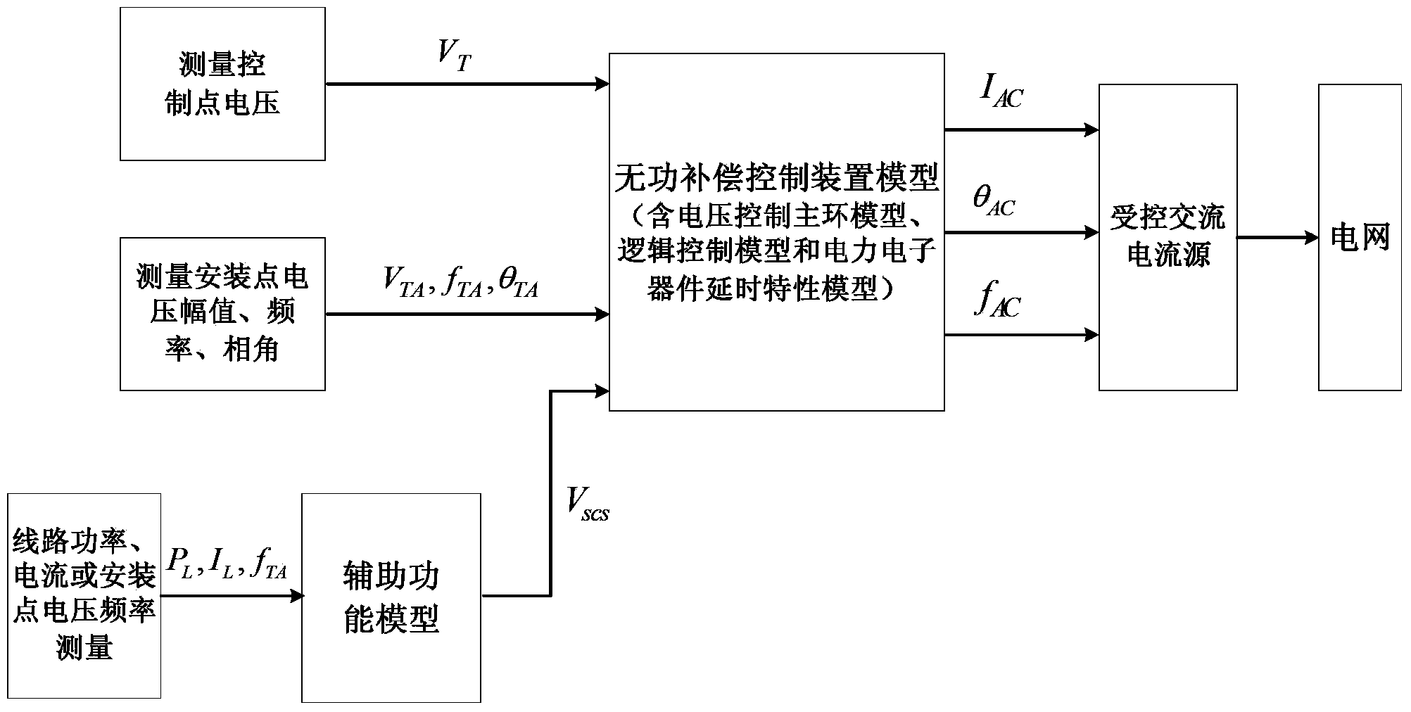
[0101] Figure 4 It is a schematic diagram of the structure of the controlled AC current source in the reactive power compensation device, where I AC is the current amplitude injected into the controlled AC current source; at Figure 5 In the commonly used two-area four-machine simulation system shown, the method proposed by the present invention is used to establish the SVC control device model, and is connected to the bus 8 through a transformer, and a three-phase short circuit occurs at the midpoint of a return line between the bus 7-8 In the case of a fault, the voltage of the control point and the output power of the SVC with / without SVC are as follows: Figure 6 and Figure 7 shown. From Figure 6 It can be seen that the realized SVC can effectively support the voltage of the controlled bus; from Figure 7 It can be seen that the active power output by the realized SVC is maintained near 0, and the output reactive power can meet the requirements of voltage control a...


PUM


Abstract

The invention provides a method for setting up a reactive power compensation device model based on a controlled alternating current source. The method includes the following steps of measuring the voltage of an installation point of a reactive power compensation device and the voltage of a control point of the reactive power compensation device, calculating control voltage deviation, setting up the reactive power compensation device model, and conducting calculating to obtain an amplitude signal, a frequency signal and a phase angle signal of the controlled alternating current source. According to the method, by using the controlled alternating current source and a grid interface, by controlling the amplitude, the phase angle and the frequency of the current of the controlled alternating current source and particularly by keeping the phase angle of the current of the installation point 90 electrical degrees greater than the phase angle of the alternating current source, the ideal control of the output power of the reactive power compensation device is achieved. The method can be easily and extensively applied to various power generation systems which include wind turbine generators, photovoltaic power generating systems, battery energy storage systems, ocean power generating systems, micro gas turbines and the like and are connected with a power grid through power electronic equipment interfaces, and can be easily and extensively applied to novel power electronic interface new energy power generating systems which are rapidly developing and constantly emerging.

Description

technical field [0001] The invention belongs to the technical field of power systems, and in particular relates to a modeling method of a reactive power compensation device model based on a controlled alternating current source. Background technique [0002] Since the 1980s, the application of flexible AC transmission system (FACTS) technology in power systems has become a research hotspot. Among them, static var compensator (SVC) and static synchronous Functions such as low-frequency oscillation and voltage flicker have been more and more researched and applied, and SVC and STATCOM devices with high voltage level and large capacity are continuously used in my country's power system. SVC integrates capacitors or reactors into the grid or disconnects them from the grid by controlling two anti-parallel thyristors, so as to generate or absorb reactive power. Its composition includes: thyristor controlled reactor (TCR), thyristor controlled high impedance transformer (TCT), thyr...

Claims


Application Information

Patent Timeline
IPC IPC(8): H02J3/18G06F17/50
CPCY02E10/56Y02E40/10
Inventor 赵大伟姜达军朱凌志张磊钱敏慧赵亮曲立楠陈宁王湘艳
Owner STATE GRID CORP OF CHINA
Why Eureka
Try Eureka