LED array visible light communication system and method

A technology of visible light communication and LED array, applied in the field of visible light communication, to achieve the effects of easy implementation, suppression of peak-to-average ratio, and obvious frequency domain diversity gain

Active Publication Date: 2013-12-18
SOUTHEAST UNIV
View PDF4 Cites 22 Cited by
  • Summary
  • Abstract
  • Description
  • Claims
  • Application Information

AI Technical Summary

Problems solved by technology

However, due to the real-number requirements of the baseband signal in the visible light channel, the traditional DFT-S structure is no longer suitable for visible light communication. It is necessary to improve the system structure s...

Method used


Image

  • LED array visible light communication system and method
  • LED array visible light communication system and method
  • LED array visible light communication system and method

Examples


Embodiment Construction

[0048] The present invention will be further described below in conjunction with the accompanying drawings.

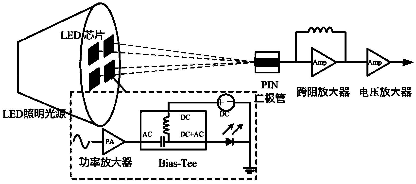
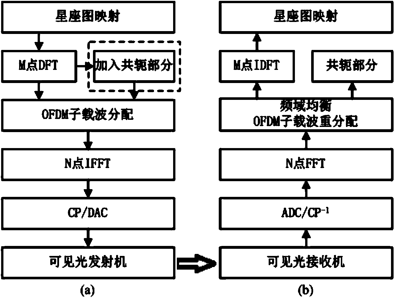
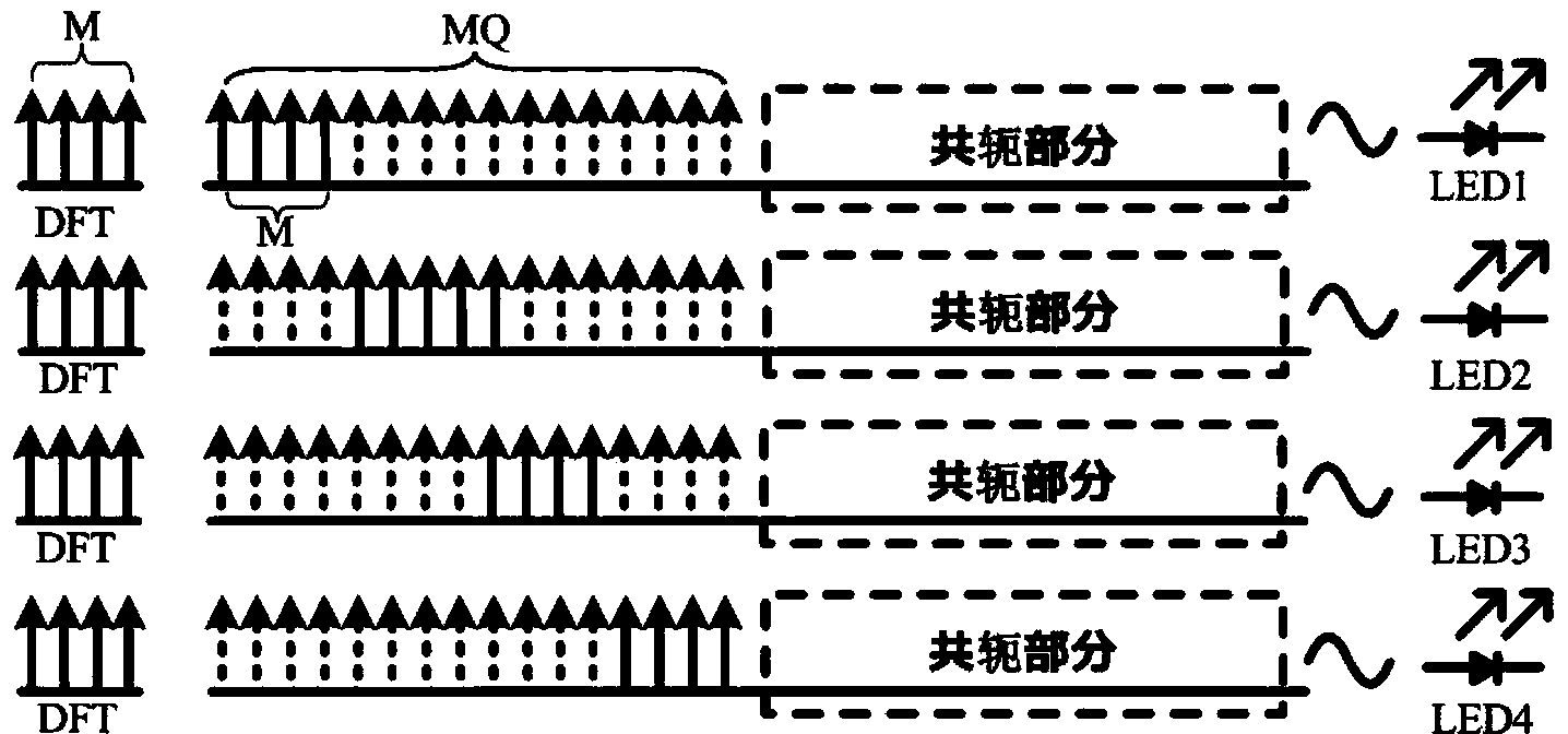
[0049] Such as figure 1 As shown, in the DFT-S OFDM-based LED array visible light communication system provided by the present invention, the transmitting end includes a DFT-S-OFMA modulator and at least one LED driver module. The DFT-S-OFMA modulator is used to perform DFT on the input data - S-OFMA modulation, and generate an electrical signal to send to the LED driver module; the LED driver module is used to convert the received electrical signal into an optical signal.

[0050] The receiving end includes a PIN receiver and a DFT-S-OFMA demodulator. The PIN receiver is used to receive the optical signal sent by the transmitting end, and convert it into an electrical signal and send it to the DFT-S-OFMA demodulator; DFT-S-OFMA The demodulator is used to perform DFT-S-OFMA demodulation on the received electrical signal.

[0051] The transmitter uses an LED lighting ...


PUM


Abstract

The invention discloses an LED array visible light communication system based on DFT-S OFDM and an LED array visible light communication method. An LED light source composed of a plurality of LED chips serves as the emitting end, and the LED chips are independently driven to form LED array emitting systems which do not disturb each other. The DFT-S OFDM modulation mode is adopted by each LED emitter, the LED emitters occupy different OFDM frequency band resources respectively, circumference conjugate symmetry is applied to OFDM frequency domain subcarriers to guarantee real number property of OFDM base band data, and a centralized DFT-S OFDM mode and a staggered DFT-S OFDM mode are applied to the visible light communication system. The DFT-S technology applied to the LED array visible light communication system based on DFT-S OFDM and the LED array visible light communication method can obviously restrain the peak-to-average power ratio of the visible light communication system, obvious frequency domain diversity gains are acquired in the aspect of bit error rate performance, and the LED array emitting structure protects system transmission ratio against effect.

Description

technical field [0001] The present invention relates to the technical field of visible light communication, in particular to a DFT-S OFDM-based LED array visible light communication system and a method thereof. Background technique [0002] In recent years, visible light communication has become a hot field in wireless communication. Compared with traditional radio communication, visible light communication is a greener and healthier communication method than radio waves. At the same time, it also has the advantages of richer spectrum resources, higher confidentiality, and no need for licenses. [0003] Indoor visible light communication research is dedicated to combining high-speed wireless data transmission with common indoor lighting. In order to provide sufficient light intensity, most of the existing indoor LED lighting sources are composed of multiple LED chips. By independently modulating and driving each LED chip on a light source, an LED array system can be formed...

Claims


Application Information

Patent Timeline
IPC IPC(8): H04B10/116H04B7/005
Inventor 张华吴超培许威
Owner SOUTHEAST UNIV
Why Eureka
Try Eureka