Weld overlay structure and a method of providing a weld overlay structure

A welding structure and welding bead technology, applied in welding equipment, transportation and packaging, arc welding equipment, etc., can solve the problems of increased heat input, harmfulness, poor fusion of overlapping weld beads, etc., to reduce heat accumulation and reduce high surface temperature. , the effect of improving durability

Active Publication Date: 2013-12-18
FOSTER WHEELER NORTH AMERICA CORP +1
View PDF11 Cites 7 Cited by
  • Summary
  • Abstract
  • Description
  • Claims
  • Application Information

AI Technical Summary

Problems solved by technology

However, this results in increased heat input to the cladding and further dilution of the weld metal
In general, cooler welds can also lead to poor fusion between overlapping beads or to the base material, which is especially detrimental when it is necessary to bend the tube
If detected, the defective surface texture that opens during bending can be repaired, for example by using additional heat input from GTAW, but this in turn produces a more undesirable Cr dilution

Method used


Image

  • Weld overlay structure and a method of providing a weld overlay structure
  • Weld overlay structure and a method of providing a weld overlay structure
  • Weld overlay structure and a method of providing a weld overlay structure

Examples


Embodiment Construction

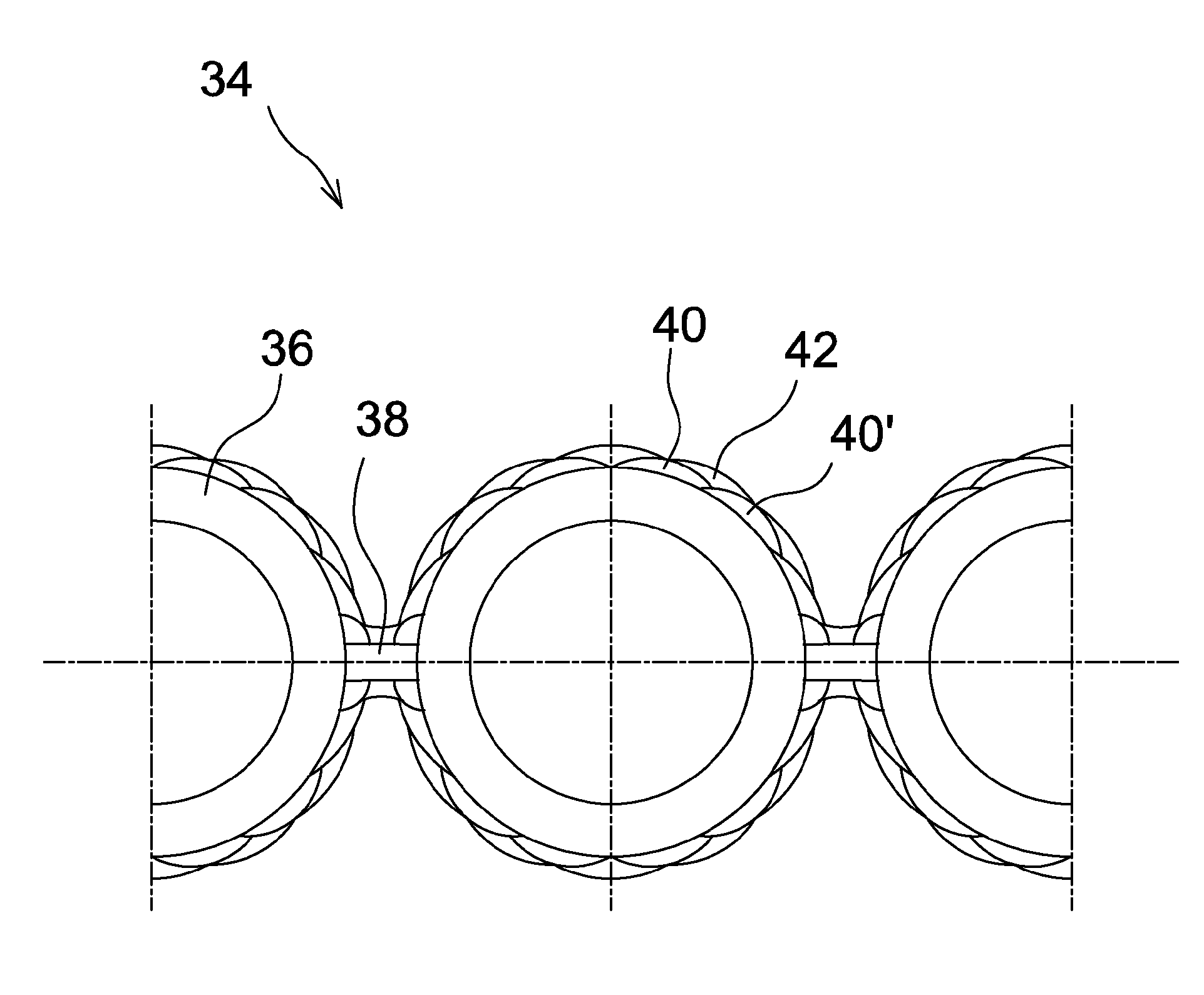
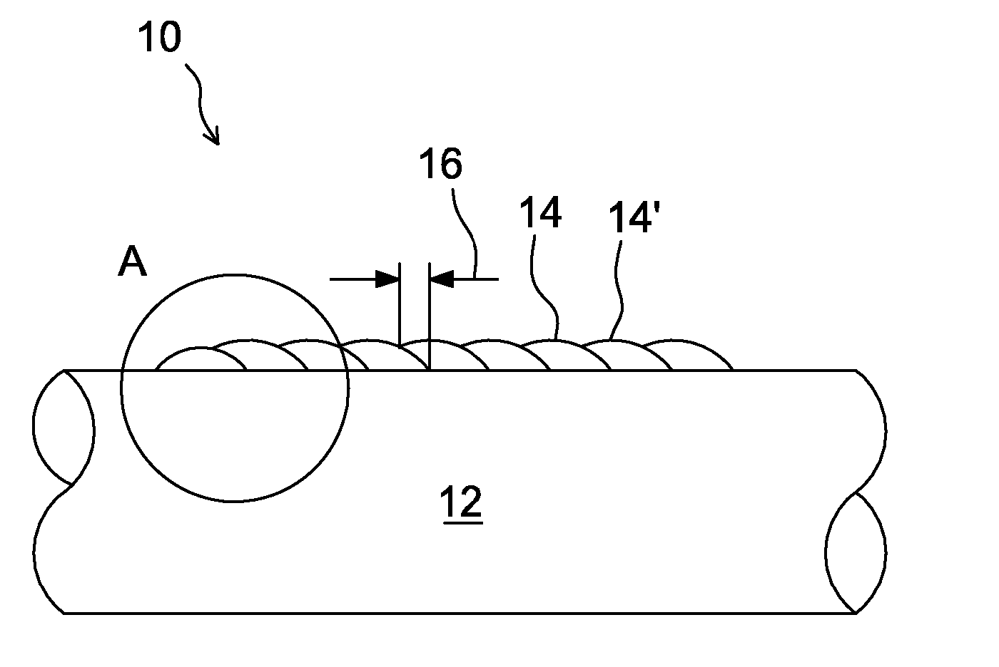
[0031] Figure 1a A schematic cross section of a conventional helical weld overlay 10 or a 360 degree weld overlay on a heat transfer tube 12 is shown. Weld overlays are formed by applying a continuous bead of weld as a helix on the outer surface of the tube. Conventionally, successive turns of the helix 14, 14N have a relatively large overlap 16, typically from about 30% to about 50% or from about 6mm to about 10mm.

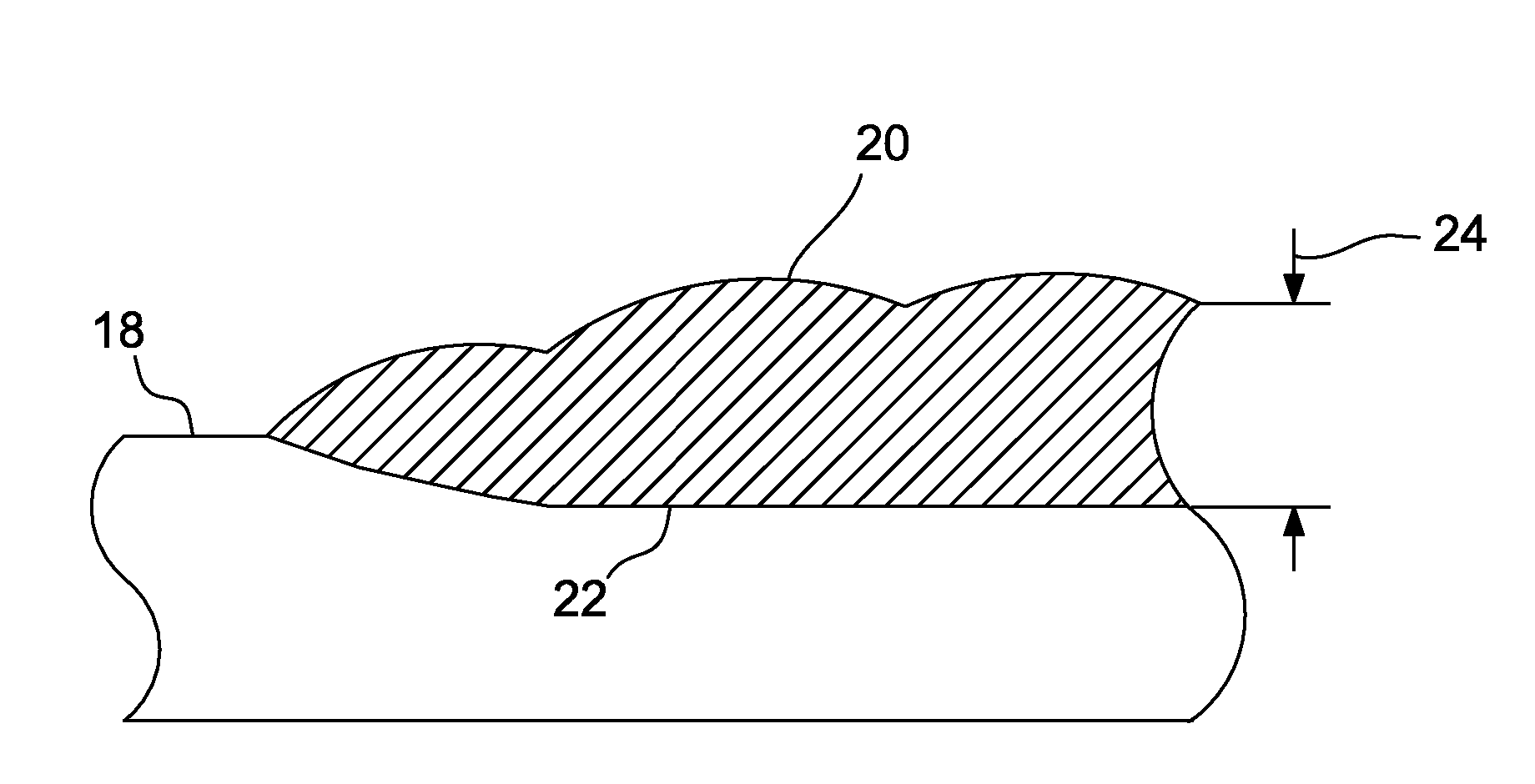
[0032] Figure 1b show Figure 1a A schematic enlarged view of detail A. In addition to the original outer surface 18 of the tube and the outer surface 20 of the weld overlay formed, Figure 1b Also shown are fusion lines 22 , the inner surfaces of the layers formed by welding. The fusion line extends within the original pipe as the base metal pipe material partially melts and mixes with the high alloy weld material.

[0033] as in Figure 1a and 1b As shown in , a cladding layer with a relatively rough as-welded outer surface and a relatively large thickne...


PUM

PropertyMeasurementUnit
thicknessaaaaaaaaaa

Abstract

A method of providing a weld overlay structure (10) on a heat transfer tube (12) or a membrane surface. A first continuous bead portion (26, 40) of an overlay material is applied onto the heat transfer tube or membrane surface by using a weld head to melt the overlay material. A second continuous bead portion (26', 40') of the overlay material is applied onto the heat transfer tube or membrane surface by using a weld head to melt the overlay material, in which the second bead portion partially overlaps with the first bead portion, forming a groove (30) between the first bead portion and the second bead portion. A third continuous bead portion (32, 42) of an overlay material is applied onto the heat transfer tube or membrane surface by using a weld head to melt the overlay material into the groove (30) between the first bead portion and the second bead portion, so as to form a relatively smooth surface.

Description

technical field [0001] The present invention relates to weld overlays and methods of providing weld overlays on heat transfer tube or membrane surfaces. In particular the invention relates to a method and a weld overlay for providing a weld overlay on the surface of a heat transfer tube or membrane which is or is to be used in a boiler but which may also be applied in chemical process vessels or marine applications. Background technique [0002] Conventional membrane surfaces or water walls made of parallel tubes joined together by metal strips (so-called fins) to form walls forming eg furnace housings are typical examples of heat transfer surfaces for power boilers. High pressure water flows inside the tubes to extract heat from the high temperature combustion gases on the outer surfaces of the tubes. Water pipes and membrane surfaces in different boilers such as biomass fired boilers, coal fired boilers, refuse derived fuel (RDF) boilers, black liquor recovery boilers or ...

Claims


Application Information

Patent Timeline
Patent Type & Authority Applications(China)
IPC IPC(8): B23K9/04F22B37/10
CPCB23K9/048B23K2101/14F22B37/025F22B37/108Y10T428/12333Y10T428/12451B33Y30/00
Inventor J.墨菲李海生
Owner FOSTER WHEELER NORTH AMERICA CORP
Why Eureka
Try Eureka