Testing system of optical fiber network

A test system and optical fiber network technology, applied in the direction of measuring electricity, measuring devices, measuring electrical variables, etc., can solve the problem that the configuration program cannot be adjusted in time to optimize the working point and related configuration programs, the testing process is cumbersome, and the engineering cycle is long. problems, to achieve the effect of short test engineering cycle, large storage capacity and long service life

Inactive Publication Date: 2013-12-25
CHENGDU CHENGDIAN GUANGXIN TECH
View PDF5 Cites 5 Cited by
  • Summary
  • Abstract
  • Description
  • Claims
  • Application Information

AI Technical Summary

Problems solved by technology

[0009] In order to overcome the prior art when testing FPGA and writing configuration program through JTAG, JTAG is used to pre-program EPROM, then install it on FPGA, and then test FPGA system or each component as a whole through JTAG. The cycle is long, and the configuration program

Method used


Image

  • Testing system of optical fiber network

Examples


Embodiment 1

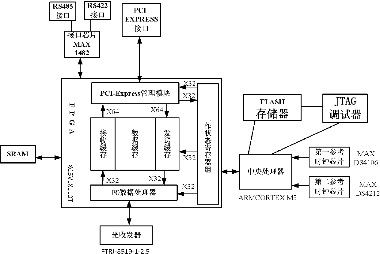
[0050] like figure 1 Shown, the present invention comprises the first reference clock chip, the second reference clock chip, also includes central processing unit, optical transceiver, FPGA field programmable gate array, FLASH memory, JTAG debugger, the first reference clock chip, the second The second reference clock chip, FLASH memory, and JTAG debugger are all connected to the central processing unit, the JTAG debugger is connected to the FLASH memory, and the central processing unit and optical transceiver are all connected to the FPGA field programmable gate array.

[0051] Those skilled in the art can freely select the parameters of the components according to the actual construction environment and the requirements of the workpiece.

Embodiment 2

[0053] In order to improve the system structure optimization capability of the test system of the optical fiber network, the present embodiment is further improved on the basis of the first embodiment, the FPGA field programmable gate array of the present embodiment includes FC data processor, data cache, PCI-Express processing The FC data processor, the data buffer and the PCI-Express processor are all connected to the working status register group, the FC data processor is connected to the data cache, and the data cache is connected to the PCI-Express processor.

[0054] Those skilled in the art can freely select the parameters of the components according to the actual working environment and design requirements.

Embodiment 3

[0056] In order to improve the data transmission capability of the test system of the optical fiber network, this embodiment is further improved on the basis of Embodiment 2. The data buffer of this embodiment includes a receiving buffer and a sending buffer, and the PC data processor is connected to the receiving buffer, and the receiving buffer is connected to A PCI-Express processor, the PCI-Express processor is connected to a sending buffer, and the sending buffer is connected to a PC data processor.

[0057] Those skilled in the art can freely select the ratio of the receiving buffer and the sending buffer of the data buffer according to actual requirements.


PUM


Abstract

The invention discloses a testing system of an optical fiber network, and belongs to the technical field of optical fiber communication transmission. The testing system comprises a first reference clock chip and a second reference clock chip, and further comprises a central processing unit, an optical transceiver, an FPGA, an EPROM and a JTAG debugger, wherein the first reference clock chip and the second reference clock chip are both connected with the central processing unit, the central processing unit, the EPROM, the JTAG debugger and the optical transceiver are all connected with the FPGA, and the JTAG debugger is connected with the EPROM. By means of the testing system, each module of the FPGA can be tested, configuration programs can be directly written in the EPROM, the engineering period is short, and the development can be conveniently and flexibly realized.

Description

technical field [0001] The invention relates to the technical field of optical fiber communication transmission, in particular to an optical fiber communication measurement, control or signal transmission system. Background technique [0002] Optical fiber communication is a communication method that uses optical fibers to transmit signals to achieve information transmission. A pair of single-mode optical fibers can open 35,000 calls at the same time. Compared with electrical communication, it has transmission frequency bandwidth, low transmission loss, uniform loss and is not affected by temperature, strong anti-interference ability, high fidelity, and high signal security. , High working reliability, etc., the high-speed serial transmission protocol adopted by it has the characteristics of high reliability, high bandwidth, and high real-time performance. With the advancement of optical fiber technology, especially the development of full-wave window optical fibers without...

Claims


Application Information

Patent Timeline
IPC IPC(8): G01R31/3177G01R31/3185
Inventor 胡钢邱昆
Owner CHENGDU CHENGDIAN GUANGXIN TECH
Why Eureka
Try Eureka