Check patentability & draft patents in minutes with Patsnap Eureka AI!

Projection optical system

A projection optical system and correction system technology, applied in optics, optical components, microlithography exposure equipment, etc., can solve the problems of increased processing, detection and assembly costs, large number of lenses, complex structure, etc., to reduce the difficulty of positioning control , good imaging quality and simple system structure

Inactive Publication Date: 2015-06-24
INST OF OPTICS & ELECTRONICS - CHINESE ACAD OF SCI
View PDF6 Cites 0 Cited by
  • Summary
  • Abstract
  • Description
  • Claims
  • Application Information

AI Technical Summary

Problems solved by technology

At present, the lithography machine with a working wavelength of 193nm has become the core component of the device in the semiconductor equipment. The world's three major lithography machine manufacturers Germany Zeiss (Zeiss), Japan Nikon (Nikon) and Canon (Canon) announced the NA0.75 Projection optical system, the conjugate distance of the system is long, the structure is complex, and the number of lenses used is large, which greatly increases the cost of processing, testing and assembly

Method used


Image

  • Projection optical system
  • Projection optical system
  • Projection optical system

Examples


Embodiment Construction

[0023] In order to better illustrate the purpose and advantages of the present invention, the specific implementation manners of the present invention will be further described below in conjunction with the accompanying drawings.

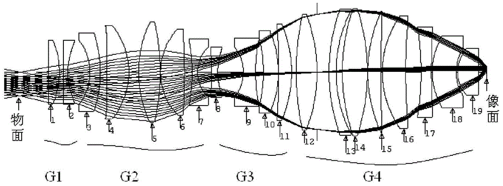
[0024] figure 1 It is a structural schematic diagram of the projection optical system of the present invention. The projection optical system is used to project the pattern in the object plane onto the image plane. The first lens group G1, the second lens group G2, and the third lens are arranged along the optical axis direction of the projection optical system. The group G3, the fourth lens group G4, and the first lens group G1, the second lens group G2, the third lens group G3, and the fourth lens group G4 are on the same optical axis, and the first lens group G1 has negative Refractive power, the second lens group G2 has positive refractive power, the third lens group G3 has negative refractive power, and the fourth lens group G4 has positive ref...


PUM

PropertyMeasurementUnit
refractive indexaaaaaaaaaa

Abstract

The invention provides a projection optical system, which is used for imaging an image of an object plane to an image plane. The system sequentially arranges a first lens group, a second lens group, a third lens group and a fourth lens group along the optical axis, and the four lens groups are on the same optical axis. The first lens group has negative refractive power, the second lens group has positive refractive power, the third lens group has negative refractive power, and the fourth lens group has positive refractive power. The projection optical system of the present invention can not only effectively reduce the conjugate distance of the system and the number of lenses, but also reduce the processing, testing, and assembly costs of the system. rate and high image quality requirements.

Description

technical field [0001] The invention relates to a projection optical system in an exposure system, in particular to a high-resolution projection optical system. Background technique [0002] Entering the 21st century in the information age, the semiconductor industry still plays a pivotal role in the information industry. With the continuous development of the semiconductor industry, semiconductor equipment manufacturers must strive to control costs while pursuing higher performance of equipment, so as to keep pace with Moore's Law proposed by Gordon E. Moore, one of the founders of Intel Corporation. This has driven the lithography machine, the core equipment in the semiconductor industry, to continue to revolutionize. With the continuous change of lithography machines, the requirements for the resolution of lithography machines are getting higher and higher. According to Rayleigh's law, reducing the wavelength of the projection optical system, reducing the process factor...

Claims


Application Information

Patent Timeline
Patent Type & Authority Patents(China)
IPC IPC(8): G02B27/18G02B27/00G02B7/04G03F7/20
Inventor 冉英华邢廷文林妩媚吕保斌陈红丽张海波白瑜
Owner INST OF OPTICS & ELECTRONICS - CHINESE ACAD OF SCI
Features
  • R&D
  • Intellectual Property
  • Life Sciences
  • Materials
  • Tech Scout
  • Unparalleled Data Quality
  • Higher Quality Content
  • 60% Fewer Hallucinations
Learn More