
Method for measuring carbon concentration in polycrystalline silicon

A determination method and technology for polysilicon, which can be used in measurement devices, color/spectral properties measurement, material analysis by optical means, etc., can solve the problems of small effective segregation coefficient of carbon impurities and difficulty in accurately measuring the carbon concentration of polysilicon.

Inactive Publication Date: 2013-12-25
SHIN ETSU CHEM CO LTD
View PDF9 Cites 13 Cited by
  • Summary
  • Abstract
  • Description
  • Claims
  • Application Information

AI Technical Summary

Problems solved by technology

[0007] However, when using this method, due to the small effective segregation coefficient (k eff =0.07, refer to Non-Patent Document 3), so when the single crystal silicon rod grown by the FZ method is short, there is a problem that it is difficult to accurately measure the carbon concentration in the polycrystalline silicon used as the raw material

Method used


Image

  • Method for measuring carbon concentration in polycrystalline silicon
  • Method for measuring carbon concentration in polycrystalline silicon
  • Method for measuring carbon concentration in polycrystalline silicon

Examples


preparation example Construction

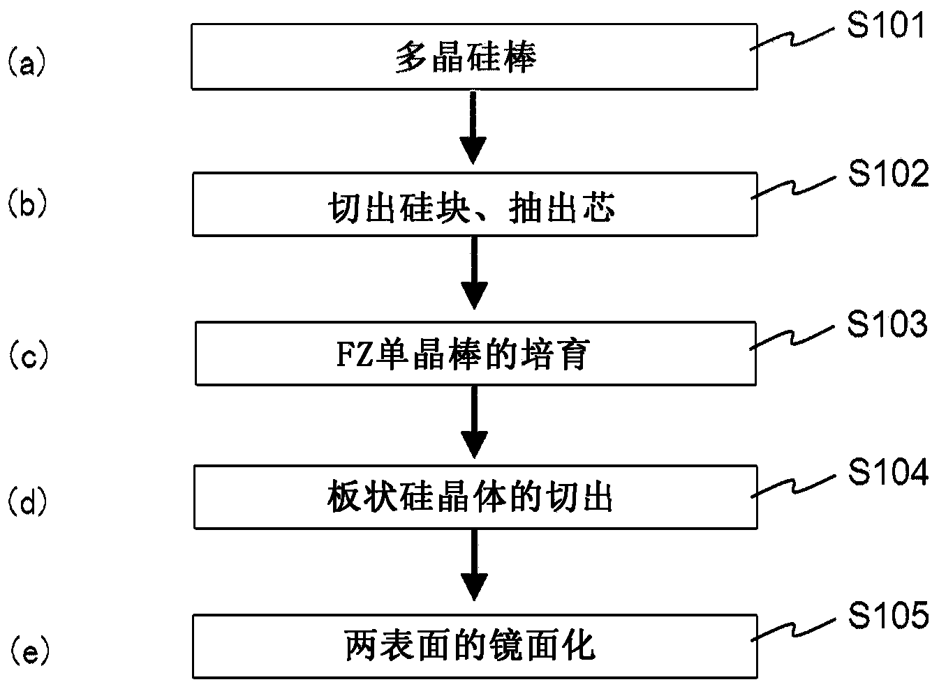
[0032] Preparation of samples for carbon concentration measurement: figure 1 It is a figure which shows an example of the preparation procedure of the sample for carbon concentration measurement. First, six polycrystalline silicon rods obtained by vapor phase growth by the Siemens method were prepared ( S101 ). For these polycrystalline silicon rods, cores (silicon blocks) each having a length of 150 mm and a diameter of 20 mm were extracted in a cylindrical shape from the longitudinal direction ( S102 ). Hereinafter, these are called cores 1-6. Next, FZ single crystal silicon rods having a diameter of approximately 10 mm and a length of approximately 200 mm are grown by using the aforementioned cores 1 to 6 as raw materials ( S103 ).

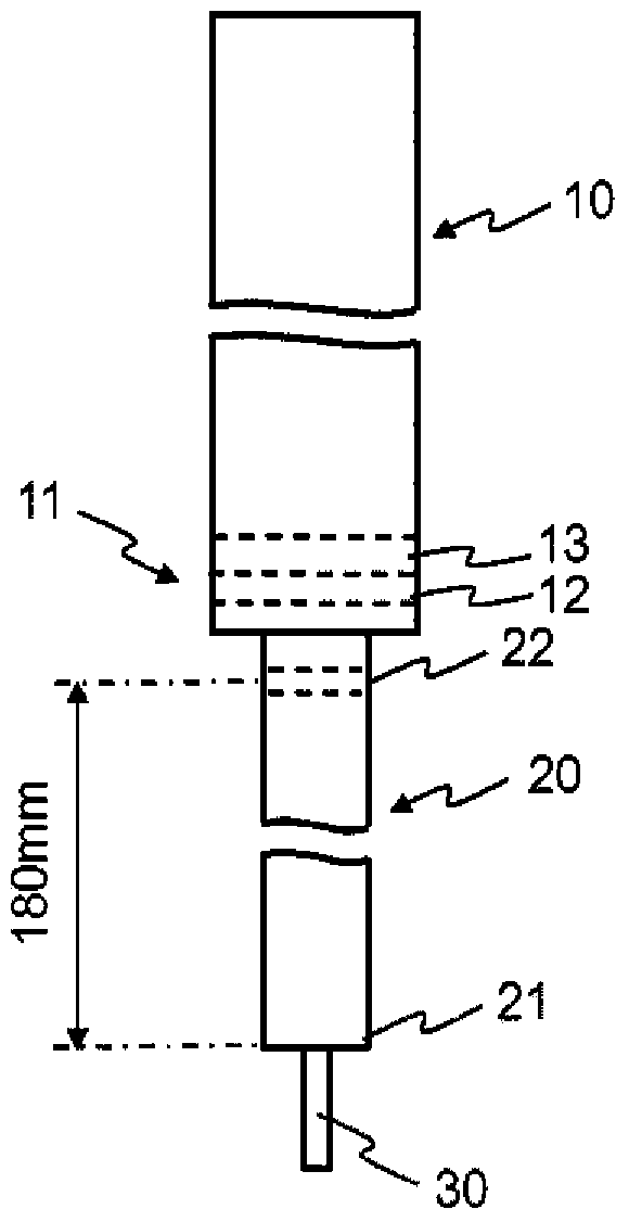
[0033] figure 2 It is a diagram for explaining cutting out a plate-shaped silicon crystal from an FZ single crystal silicon rod and a holding part. In this figure, symbol 10 is a core (silicon block), symbol 20 is an FZ single crystal silic...

Embodiment

[0050] Example: According to the above steps, one piece of plate-shaped FZ monocrystalline silicon with a thickness of 2.000 mm and one piece of plate-shaped polysilicon with a thickness of 2.006 mm and 2.477 mm were prepared from polycrystalline silicon rods, and mirror grinding was performed on both surfaces.

[0051] The transmission spectra of these samples were measured, and the carbon concentration of each sample was determined. As a result, the plate-shaped FZ single crystal silicon was 0.08758 ppma, and the plate-shaped polycrystalline silicon with thicknesses of 2.006 mm and 2.477 mm were -0.06909 ppma and 0.56866 ppma, respectively.

[0052] A second calibration curve was prepared from the carbon concentration value -0.06909ppma of plate-shaped polysilicon with a thickness of 2.006mm and the carbon concentration value of 0.56866ppma in plate-shaped polysilicon with a thickness of 2.477mm, and the thickness of the second calibration curve was obtained as 2.00±0.01mm Th...


PUM

PropertyMeasurementUnit
lengthaaaaaaaaaa
diameteraaaaaaaaaa
diameteraaaaaaaaaa

Abstract

The present invention provides a method with which it is possible to measure the approximate concentration of substitutional carbon impurities easily and simply and at a desired location in a polycrystalline silicon rod. A polycrystalline silicon plate is cut out from a polycrystalline silicon rod. Both surfaces of the polycrystalline silicon plate are mirror-polished to a thickness of 2.12+-0.01 mm. A calibration curve is created in accordance with a standard measurement method through infrared absorption spectroscopy by employing a monocrystalline silicon standard sample having a known substitutional carbon concentration and a thickness of 2.00+-0.01 mm. An infrared absorption spectrum in the wave number range including the absorption band peak of substitutional carbons in the mirror-polished polycrystalline silicon plate is obtained under the same conditions as those employed at the time of creating the calibration curve, and the substitutional carbon concentration is found without performing thickness correction.

Description

technical field [0001] The invention relates to a method for measuring carbon concentration in polysilicon. Background technique [0002] A silicon substrate can generally be used as a substrate for a semiconductor device or a substrate for a solar cell. Polysilicon produced by the Siemens method can be used as a raw material for such a silicon substrate. However, as the requirements for high integration and high quality of final products become stricter, the requirements for high purity of polysilicon are also becoming stricter. [0003] As a light element impurity in silicon crystals, interstitial oxygen or substitutive carbon is known. Interstitial oxygen precipitates in the crystal, causing dislocations or stacking faults. Substitutional carbon is an impurity that promotes the precipitation of this oxygen, so its concentration has been studied As for the measurement method, for single crystal silicon, a standard measurement method using Fourier transform infrared spectr...

Claims


Application Information

Patent Timeline
Patent Type & Authority Applications(China)
IPC IPC(8): G01N21/35G01N21/00G01N21/27G01N21/3563
CPCG01N21/274G01N21/3563G01J3/42
Inventor 冈田淳一小林幸一久米史高
Owner SHIN ETSU CHEM CO LTD
Learn More