Device and method for impacting and strengthening fastening hole through ring laser

A technology of laser shock strengthening and fastening holes, which is applied in the field of impact strengthening fastening holes, can solve the problems of limited size of fastening holes that can be strengthened, deformation of the edges of fastening holes, and non-utilization of fatigue performance, etc., to achieve convenient Promote the use, improve fatigue performance, and improve the effect of laser power density

Active Publication Date: 2014-01-01
AVIC BEIJING AERONAUTICAL MFG TECH RES INST
View PDF6 Cites 11 Cited by
  • Summary
  • Abstract
  • Description
  • Claims
  • Application Information

AI Technical Summary

Problems solved by technology

[0003] From the above, the disadvantages of the existing laser shock peening method for fastening holes are: ①. The circular laser beam is used to strengthen the fastening hole coaxially. Since there is no material in the fastening hole, the effect on the fastening The laser energy at the hole position is severely limited in the size of the fastening hole that can be strengthened without changing the laser output energy; ②. When a large residual compressive stress value is required, the laser acting on the surface around the fastening hole end The power density is also higher, but the greater the laser power density, the more serious the deformation of the edge of the fastening hole, the fatigue performance is not used, so the laser power density and the deformation of the edge of the fastening hole are contradictory

Method used


Image

  • Device and method for impacting and strengthening fastening hole through ring laser
  • Device and method for impacting and strengthening fastening hole through ring laser
  • Device and method for impacting and strengthening fastening hole through ring laser

Examples


Embodiment Construction

[0026] In order to have a clearer understanding of the technical features, purposes and effects of the present invention, the specific implementation manners of the present invention will now be described with reference to the accompanying drawings.

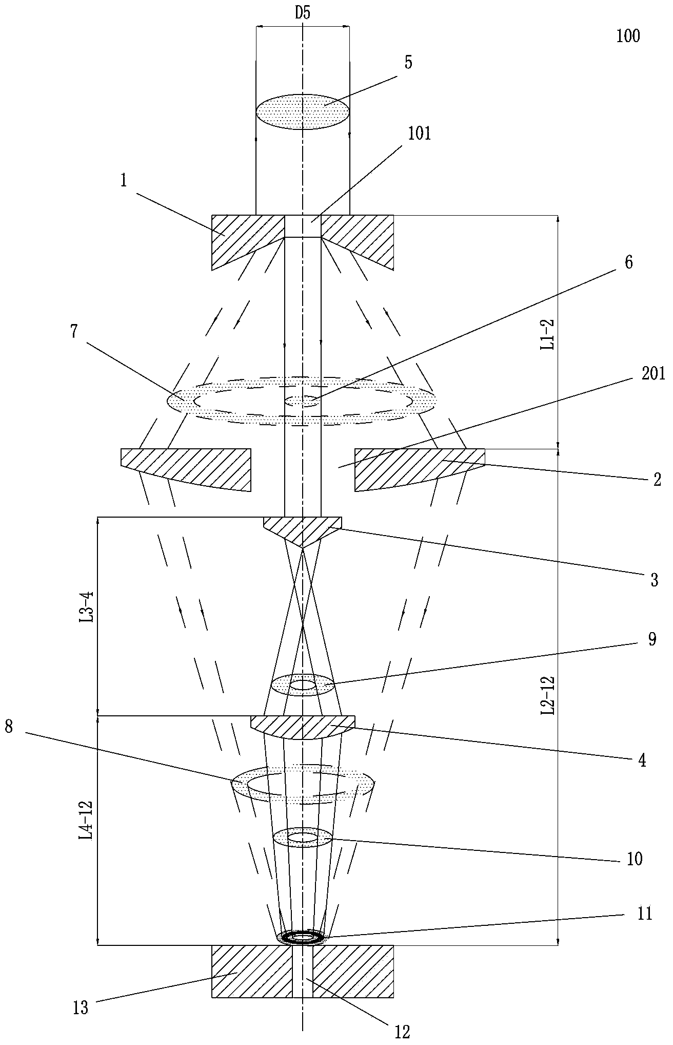
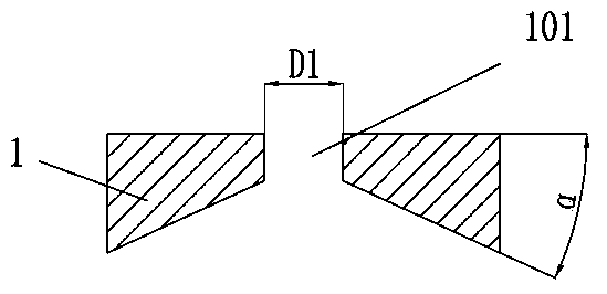
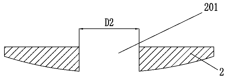
[0027] Such as figure 1 , Figure 5 As shown, the present invention proposes a device 100 for ring-shaped laser shock strengthening fastening holes. The device 100 is arranged above the object 13 for laser shock strengthening, and the object 13 for laser shock strengthening is a metal material (such as: aluminum alloy, titanium alloy, etc.), the object 13 of the laser shock strengthening is provided with a fastening hole 12; the device 100 includes a concave cone lens 1 with a central hole and a focusing lens with a central hole arranged coaxially in sequence from top to bottom 2. Convex convex lens 3 and focusing lens 4; each lens is arranged on an optical lens adjustment frame (not shown in the figure); each lens is arranged c...


PUM

PropertyMeasurementUnit
diameteraaaaaaaaaa

Abstract

The invention discloses a device and method for impacting and strengthening a fastening hole through ring laser. The device is arranged above a laser impacting and strengthening object provided with a fastening hole and comprises an inner concave cone lens provide with a center hole, a focusing lens provide with a center hole, an outer convex cone lens and a focusing lens, which are sequentially and coaxially arranged from top to bottom; the lenses are arranged on an optical lens adjusting frame; the lenses are coaxially arranged with the fastening hole; a ring laser beam with diameter larger than the aperture of the center hole of the inner concave cone lens is axially incident from the upper side of the inner concave cone lens. The device disclosed by the invention can spatially separate the ring laser beam, couple the separated ring laser beams into a new ring laser beam and regulate the spatial energy distribution of the new ring laser beam to improve the bearable laser power density, and the ring laser beam is used for impacting, strengthening, regulating and controlling the residual stress distribution on the surrounding of the fastening hole end so as to further improve the fatigue performance of the fastening hole. The device disclosed by the invention is capable of increasing the utilization rate of laser pulse energy, simple to operate and convenient to promote and use.

Description

technical field [0001] The invention relates to a device for laser shock strengthening of fastening holes, in particular to a device and method for converting circular laser beams into circular laser beams to realize shock strengthening of fastening holes. Background technique [0002] Laser shock strengthening technology uses nanosecond pulsed laser to generate plasma shock wave effect on the surface of the material, and introduces the residual compressive stress layer by causing micro-plastic deformation on the surface of the material, thereby improving the fatigue performance of metal parts. Usually, the laser shock strengthening can only be carried out after the surface of the material should be arranged with an absorbing layer (aluminum foil tape or black paint, etc.) and a constraining layer (deionized water, etc.). Laser shock strengthening is a general surface strengthening technology. Laser shock strengthening can be used for key fatigue parts or key fatigue parts o...

Claims


Application Information

Patent Timeline
Patent Type & Authority Applications(China)
IPC IPC(8): C21D10/00
Inventor 曹子文巩水利毛智勇车志刚邹世坤
Owner AVIC BEIJING AERONAUTICAL MFG TECH RES INST
Why Eureka
Try Eureka