Compression device, and thermodynamic system comprising such compression device

A compression device, compressor technology, applied in the direction of compressors, components of pumping devices for elastic fluids, pump devices, etc., can solve problems such as insufficient lubrication, damage to compressor integrity, etc., to avoid pressure Balancing the degradation of characteristics, avoiding cumulative effects

Active Publication Date: 2014-01-01
DANFOSS COMML COMPRESSORS
View PDF7 Cites 1 Cited by
  • Summary
  • Abstract
  • Description
  • Claims
  • Application Information

AI Technical Summary

Problems solved by technology

Consequently, when the compressor is subsequently started, the amount of oil contained in its oil tank may not be sufficient to

Method used


Image

  • Compression device, and thermodynamic system comprising such compression device
  • Compression device, and thermodynamic system comprising such compression device
  • Compression device, and thermodynamic system comprising such compression device

Examples


Embodiment Construction

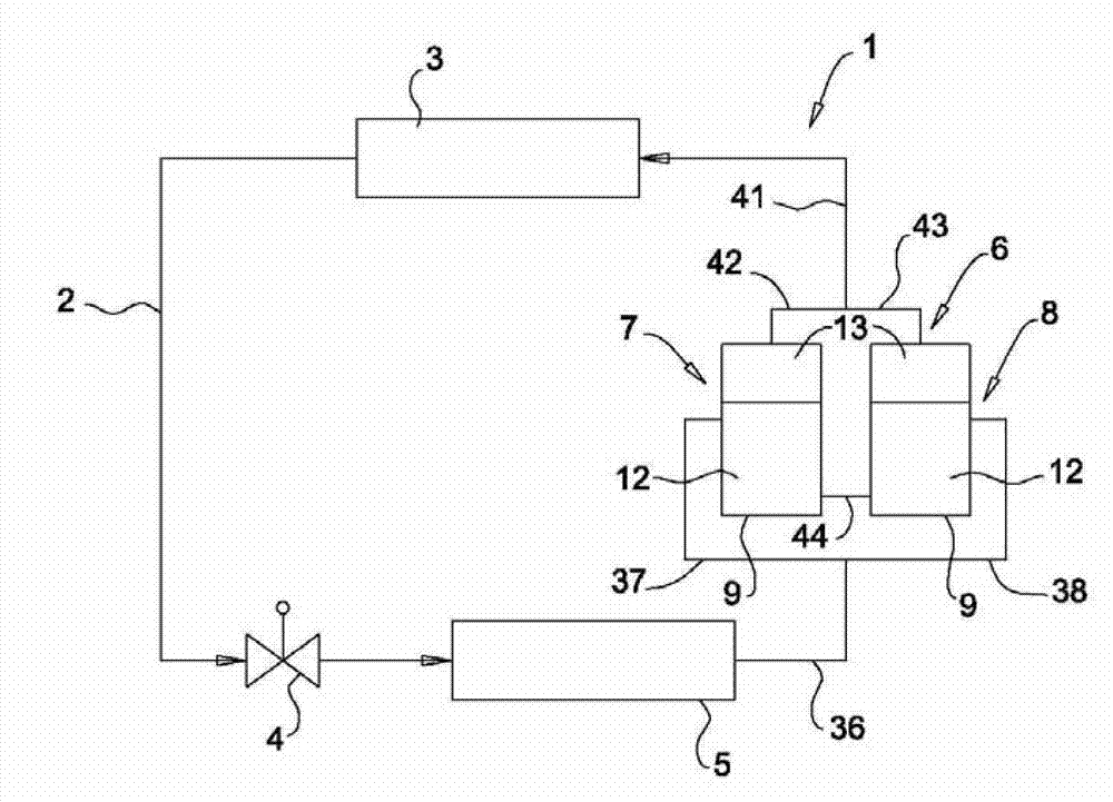
[0075] figure 1 The main components of the thermodynamic system 1 are shown schematically. The thermodynamic system 1 may be a refrigeration system, such as a reversible refrigeration system.

[0076] The thermodynamic system 1 comprises a circulation circuit 2 for a refrigerant comprising in turn a condenser 3 , an expander 4 , an evaporator 5 and a compression device 6 connected in series.

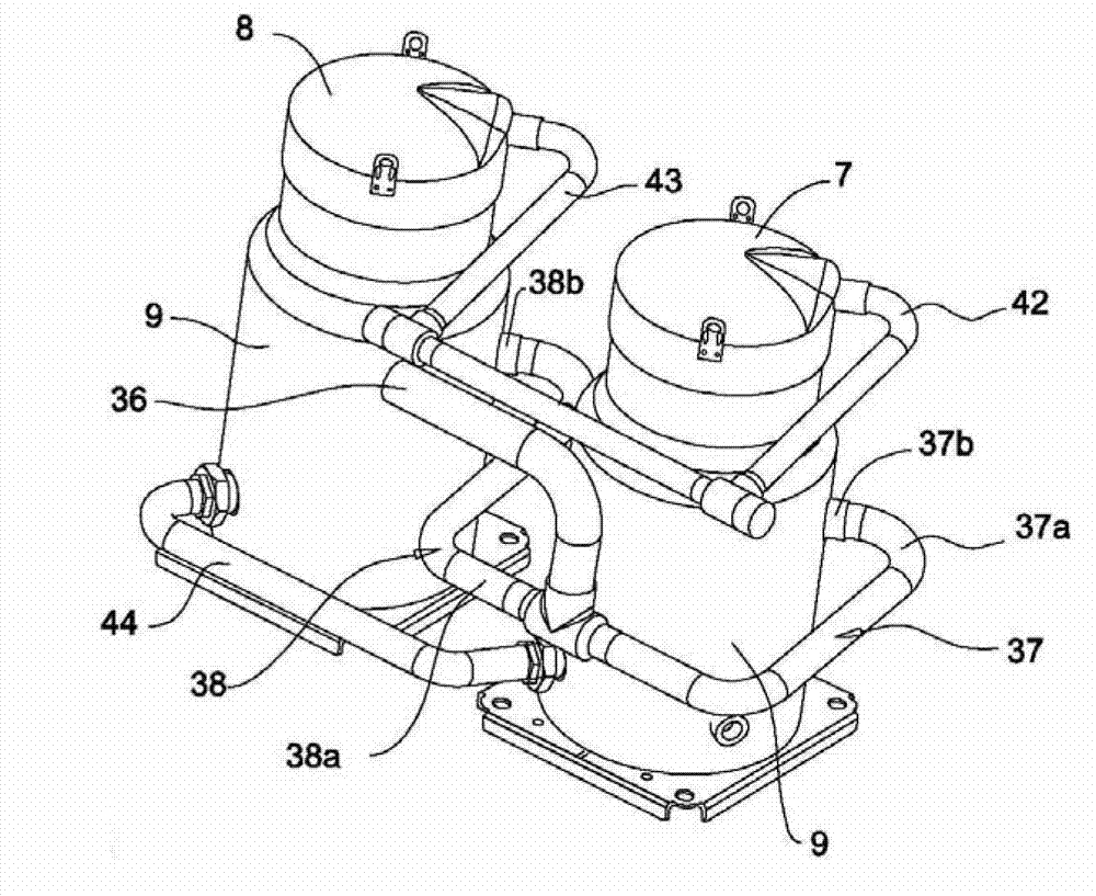
[0077] The compression device 6 comprises a first compressor 7 and a second compressor 8 installed in parallel, each compressor may have a variable capacity (more specifically variable speed) or a fixed capacity (more specifically constant speed). Advantageously, each compressor 7, 8 is a scroll compressor.

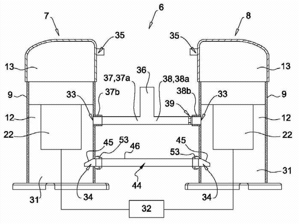
[0078] Such as Figure 4 As mentioned, each compressor 7, 8 includes a sealed casing 9 in which an organic body 11 is installed, and the body 11 defines a low-pressure area 12 below the body 11 and a high-pressure area 13 above the body 11.

[0079] Each compressor 7 , 8 include...


PUM


Abstract

The compression device according to the invention includes first and second compressors mounted in parallel and an oil level equalization line arranged to fluidly connect the oil sumps of the first and second compressors. The oil level equalization line includes at least one oil level regulating portion positioned near one of the first and second compressors and including a dam wall extending transversely to the longitudinal direction of said oil level regulating portion and a flow opening arranged such that, when the oil level in the oil sump of the compressor situated near the oil level regulating portion extends above the upper level of the dam wall, oil flows through the flow opening toward the other compressor.

Description

technical field [0001] The invention relates to a compression device, and a thermodynamic system with the compression device. Background technique [0002] As is known, the thermodynamic system in particular of refrigeration systems comprises a refrigerant circulation circuit which in turn comprises a condenser, an expander, an evaporator and a compression device connected in series. [0003] Compression devices for such thermodynamic systems typically include: [0004] - at least one first compressor and a second compressor installed in parallel therewith, each compressor comprising a hermetic casing, which in particular comprises a low-pressure zone housing an electric motor and an oil tank located at the bottom of the casing, and a high-pressure zone comprising a compression stage , [0005] - the suction line, which is connected to the evaporator, [0006] - a first suction duct communicating the suction line with the inlet port of the first compressor, and [0007] ...

Claims


Application Information

Patent Timeline
IPC IPC(8): F25B31/00
CPCF04C28/065F25B1/10F25B31/00F25B31/002F04C28/02F04C23/001F04C23/005F04B39/0207F04B49/02F04B41/06F04B23/04F25B13/00F04B39/121F25B1/02F25B31/004F25B2400/075F04C23/008F04C29/028F04C2240/806F04C2240/809
Inventor 帕垂斯·邦尼弗伊寇堪姆·罗·范亚历山大·兰德雷戴维·吉纳沃伊斯
Owner DANFOSS COMML COMPRESSORS
Why Eureka
Try Eureka