Transparent nozzle self-circulation device for internal cavity flowing visualization research

A technology of cavitation flow and nozzles, which is applied in the field of self-circulation devices, can solve problems such as leakage, and achieve the effects of high measurement accuracy, easy implementation, and good sealing

Active Publication Date: 2014-01-01
泰州市海创新能源研究院有限公司
View PDF5 Cites 16 Cited by
  • Summary
  • Abstract
  • Description
  • Claims
  • Application Information

AI Technical Summary

Problems solved by technology

However, when using the above test methods to study the internal flow characteristics of the nozzle, there are the following difficulties: first, the entire test process needs to be automatically circulated and airtight, without any leakage; second, to ensure that the test bench must be continuous, safe and stable throughout the test process Operation, to ensure that the entire test process is a quasi-static process; again, the pressure must be adjustable and precisely measured during the test; finally, the processing of the transparent nozzle must ensure pressure resistance and high precision, and at the same time, it is necessary to ensure that the parts under test are easy to disassemble.

Method used


Image

  • Transparent nozzle self-circulation device for internal cavity flowing visualization research
  • Transparent nozzle self-circulation device for internal cavity flowing visualization research

Examples


Embodiment Construction

[0018] The present invention will be described in further detail below in conjunction with the accompanying drawings.

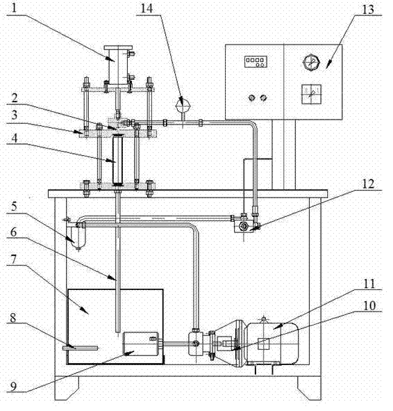
[0019] The structure of the self-circulation device for the visualization research of cavitation flow inside a transparent nozzle of the present invention is as follows: figure 1 As shown, including oil circuit system, transmission system and monitoring system.

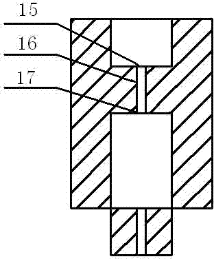
[0020] The oil circuit system is used to ensure the self-circulation flow of fuel oil. The oil circuit system includes a fuel tank 7, a coarse filter 9, a fine filter 5, an oil pressure regulating valve 12, a nozzle 2, a measuring cylinder 4, The oil return pipe 6 and the fuel tank 7 are provided with a heater 8 for opening and closing according to the needs of the test. The fuel is extracted from the fuel tank 7 and heated to the temperature required by the test by the heater 8, then passes through the coarse filter 9 and the fine filter. 5. Oil pressure regulating valve 12, nozzle 2, measuring cyl...


PUM


Abstract

The invention discloses a transparent nozzle self-circulation device for internal cavity flowing visualization research. The transparent nozzle self-circulation device comprises a back pressure system, a gas circulation system, a temperature control system and a fuel injection system. The back pressure system comprises high-pressure nitrogen, a back pressure cavity, a gas flow control valve assembly and a first pressure transmitter. The gas circulation system comprises a filter, a gas circulation compressor, a pressure resistance gas cylinder, a gas control valve, a second pressure transmitter and an electronic control pressure stabilizer. The temperature control system comprises a temperature control unit and a heat exchanger and is used for ensuring that temperature in the back pressure cavity is constant. The fuel injection system comprises a proportion amplifying fuel injector and a proportion amplifying fuel spray nozzle. The problem that in the prior art, atomized diesel fuel blurs a sight window of the back pressure reception cavity is solved, so that further development of the experiment is facilitated. By the adoption of the proportion amplifying fuel spray nozzle, a visible experiment for internal flowing of the fuel proportion amplifying fuel spray nozzle of a diesel engine under the condition of certain back pressure is made to be possible.

Description

technical field [0001] The invention particularly relates to a self-circulation device for realizing the visualization research of cavitation flow inside a transparent nozzle, which belongs to the technical field of diesel engine and hydraulic cavitation. Research. Background technique [0002] Due to its excellent fuel economy, durability and low CO2 emissions, diesel engines will continue to maintain their status as the main driving force in the transportation field in the 21st century, but their development is affected by nitrogen oxides (NOx) and particulates (PM). Challenges such as high emissions and high noise. NOx and PM are produced in the combustion process. As one of the boundary conditions of combustion, fuel spray mixing has the most direct relationship with the combustion process, thus having a decisive impact on the combustion and emission performance of diesel engines. In recent years, a large number of foreign studies have shown that the cavitation phenome...

Claims


Application Information

Patent Timeline
Patent Type & Authority Applications(China)
IPC IPC(8): G01M10/00
Inventor 钟汶君何志霞王谦邵壮
Owner 泰州市海创新能源研究院有限公司
Why Eureka
Try Eureka