Flip-chip light emitting diode and manufacturing method and application thereof
A light-emitting diode and flip-chip technology, applied in the field of chip-on-board packaging structure, can solve the problems of inability to achieve light output rate, influence luminous intensity, thermal expansion of materials, etc., so as to avoid the deterioration of photoelectric characteristics of components, improve light output rate, and improve reliability. The effect of degree and longevity
- Summary
- Abstract
- Description
- Claims
- Application Information
AI Technical Summary
Problems solved by technology
Method used
Image

Examples
Embodiment 1
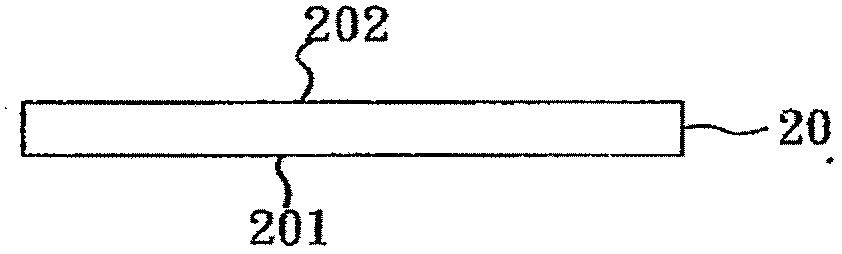
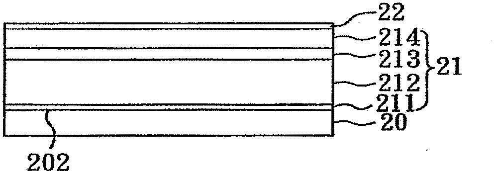
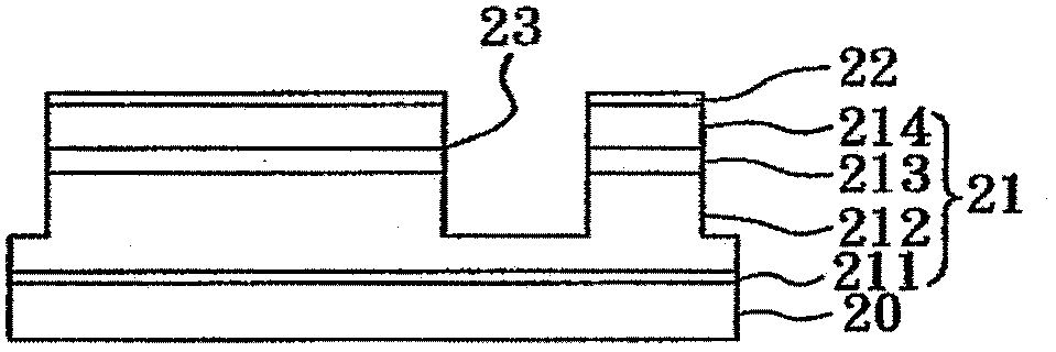
[0075] refer to Figure 1A to Figure 1H It is a schematic flow diagram of the manufacturing method of the flip-chip light emitting diode according to the first embodiment of the present invention. First, if Figure 1A As shown, a substrate 20 is provided, which has a first surface 201 and a second surface 202 opposite to the first surface 201 . Next, if Figure 2B As shown, a semiconductor epitaxial multilayer composite structure 21 is formed above the second surface 202 of the substrate 20, wherein the semiconductor epitaxial multilayer composite structure 21 includes an undoped semiconductor epitaxial layer 211, a first Semiconductor epitaxial layer 212, an active intermediate layer 213, and a second semiconductor epitaxial layer 214, wherein the undoped semiconductor epitaxial layer 211, the first semiconductor epitaxial layer 212, the active intermediate layer 213 and the The second semiconductor epitaxial layer 214 is stacked, the undoped semiconductor epitaxial layer 2...
Embodiment 2
[0085] Please refer to image 3 , which is a schematic structural diagram of a flip-chip light-emitting diode according to Embodiment 2 of the present invention. like image 3 As shown, the structure of this embodiment is substantially the same as that of the flip-chip light emitting diode of the first embodiment, which includes: a substrate 40 having a first surface 401 and a second surface 402 opposite to the first surface 401; A semiconductor epitaxial multilayer composite structure 41, which is located on the second surface 402 of the substrate 40 and the semiconductor epitaxial multilayer composite structure 41 includes an undoped semiconductor epitaxial layer 411, a first semiconductor epitaxial layer 412 , an active intermediate layer 413, and a second semiconductor epitaxial layer 414, wherein the undoped semiconductor epitaxial layer 411, the first semiconductor epitaxial layer 412, the active intermediate layer 413, and the second semiconductor epitaxial layer The ...
Embodiment 3
[0087] refer to Figure 4 , which is a structural schematic diagram of the on-chip package structure of this embodiment. like Figure 4 As shown, the chip-on-chip package structure includes: a circuit carrier 6; The circuit carrier 6 is electrically connected, wherein the circuit carrier 6 includes an insulating layer 61, a circuit substrate 60, and an electrical connection pad 63, and the material of the insulating layer 61 can be selected from diamond-like carbon, aluminum oxide, ceramics, Diamond-containing epoxy resin, or a mixture of the above materials, the circuit substrate 60 is a metal plate, a ceramic plate or a silicon substrate.
[0088] In the chip-on-board package structure, the solder 62 formed on the surface of the electrical connection pad 63 can be used to make the first metal soldering layer 29 and the second metal soldering layer 28 and the circuit carrier board through a flip-chip method. The electrical connection pad 63 of 6 achieves electrical connect...
PUM
 Abstract
Description
Claims
Application Information