
Optical fiber and fiber laser comprising optical fiber

A fiber laser and fiber technology, which is applied in the directions of multi-layer core/clad fibers, clad fibers, optical waveguides, etc., can solve problems such as unfavorable construction of high-power fiber lasers, reduction of fiber damage threshold, and reduction of laser stability. , to improve the anti-irradiation and anti-photo-darkening performance, avoid insertion loss and thermal load, and improve the stability

Inactive Publication Date: 2014-01-01
HUAZHONG UNIV OF SCI & TECH
View PDF5 Cites 12 Cited by
  • Summary
  • Abstract
  • Description
  • Claims
  • Application Information

AI Technical Summary

Problems solved by technology

[0004] In addition, most of the current fiber gratings are prepared by using the photosensitivity of germanium-doped fibers, but adding germanium to doped fibers will reduce the damage threshold of the fiber and increase the numerical aperture, which is not conducive to the construction of high-power fiber lasers. The grating is engraved on the germanium-doped passive fiber, and then fused at both ends of the doped fiber, which will increase the fusion point of the laser, increase the loss and reduce the stability of the laser

Method used


Image

  • Optical fiber and fiber laser comprising optical fiber
  • Optical fiber and fiber laser comprising optical fiber
  • Optical fiber and fiber laser comprising optical fiber

Examples


example 1

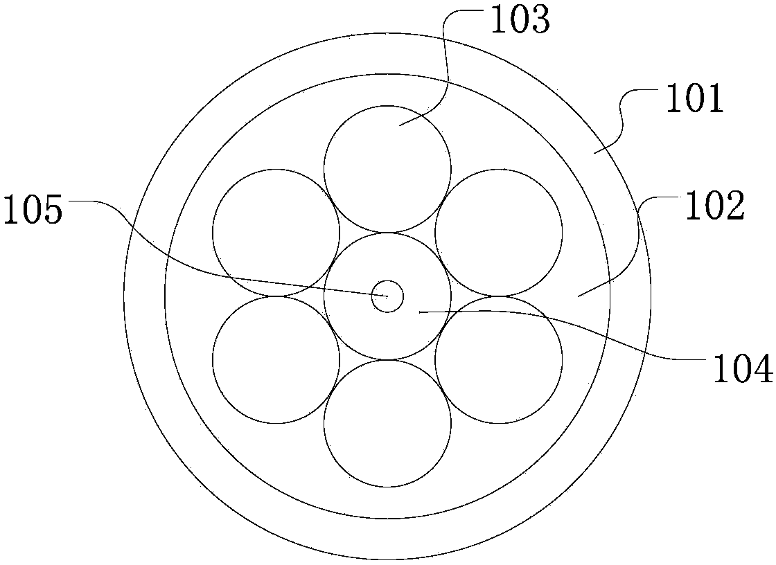
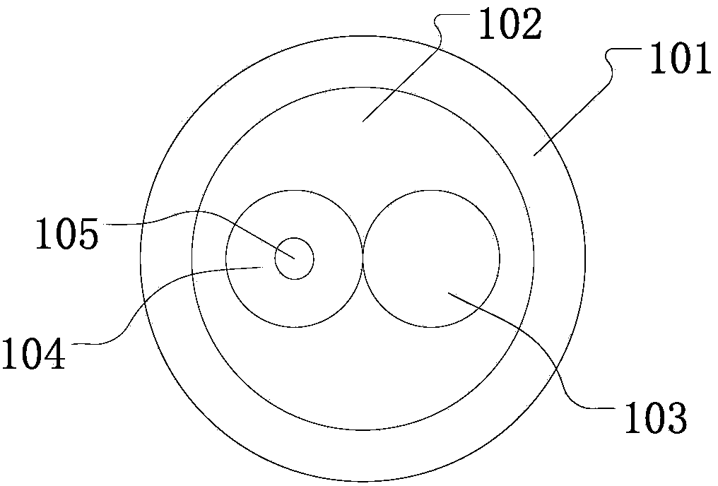
[0028] A preferred example of the present invention one, the structure is as Figure 5 As shown, first take a 20m structure such as figure 2 The new structure fiber shown, in which the gain medium of the active core is Yb 3+ , the pump core 103 has a diameter of 400 μm, the active core 104 has a diameter of 400 μm, and the doped region 105 has a diameter of 20 μm. The 20 cm coating layer at both ends is stripped off, and the two cores 103 and 104 in the fiber will naturally separate , and then write a 1080nm high reflection grating 304 at one end of the active fiber core 104, and write a 1080nm low reflection grating 303 at the other end, wherein the high reflection grating 304 has a reflectivity of 98% to 1080 nm, and the low reflection grating 303 has a 1080nm reflectivity 20%, and then the two ends of the pump core are fused with the 975nm semiconductor laser 302. When the pump power is 40W, the 1080nm laser output from the output port 301 is 28.8W.

example 2

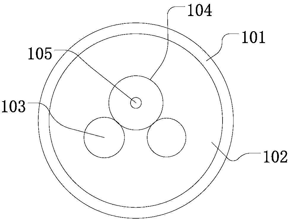
[0030] The second preferred example of the present invention has a structure such as Image 6 As shown, first take a 20m structure such as image 3 The novel structure optical fiber shown (wherein, n=2), wherein the gain medium of the active core is Yb 3+ , the pump core 103 has a diameter of 200 μm, the active core 104 has a diameter of 600 μm, and the doped region 105 has a diameter of 60 μm. The 20 cm coating layer at both ends is stripped off, and the three cores in the optical fiber will naturally separate. Then write the high reflective grating 304 of 1080nm at one end of the active fiber core 104, and write the low reflective grating 303 of 1018nm at the other end, wherein the high reflective grating 304 is 98% to 1080 reflectivity, and the low reflective grating 303 is 1080nm. 20%, and then the pump core is fused with a 915nm semiconductor laser 302. When the pumping power is 80W, the 1080nm laser output from the output port 301 is 60.8W.

example 3

[0032] The third preferred embodiment of the present invention has a structure such as Figure 5 As shown, first take the 7m structure such as Figure 4 The new structured fiber shown, where the gain medium of the active core is Tm 3+ , the pump core 103 has a diameter of 130 μm, the active core 104 has a diameter of 130 μm, and the doped region 105 has a diameter of 10 μm. The 20 cm coating layer at both ends is stripped off, and the two cores 103 and 104 in the fiber will naturally separate , and then write a high reflection grating 304 of 1950nm at one end of the active fiber core 104, and write a low reflection grating 303 of 1950nm at the other end, wherein the high reflection grating 304 has a reflectivity of 98% to 1950, and the low reflection grating 303 has a reflectivity of 1950nm 20%, and then the pump core is fused with a 793nm semiconductor laser 302. When the pumping power is 40W, the 1950nm laser output from the output port 301 is 27.4W.


PUM

PropertyMeasurementUnit
diameteraaaaaaaaaa
reflectanceaaaaaaaaaa

Abstract

The invention discloses an optical fiber and a fiber laser. The optical fiber comprises an outer cladding, a protective layer and a fiber core; the fiber core is formed by a rare earth-doped active fiber core body and n pure quartz pumping fiber core bodies, wherein the rare earth-doped active fiber core body is provided with a pure quartz inner cladding, and the n is greater than or equal to 1; each pumping fiber core body and the active fiber core body are mutually contacted but not fused together, wherein the spread length of a contact site is greater than or equal to one tenth of the perimeter of the pumping fiber core body so that light can be coupled from the pumping fiber core body to the active fiber core body in a one-way mode. The fiber laser comprises the optical fiber, a resonant cavity and a semiconductor laser body, wherein a high-reflective optical grating and a low-reflective optical grating are etched in the two ends of the active fiber core body respectively and service as the resonant cavity together; the pumping fiber core bodies are connected with the semiconductor laser body in a fusion welding mode. The optical fiber can reduce the number of fusion welding points to the maximum extent and effectively improve pumping light absorption efficiency, thereby realizing heat dissipation inside the fiber laser and improving output quality of the fiber laser; since cerium is used, the fiber laser also has the advantages of resistance to photon darkening and radiation.

Description

technical field [0001] The invention belongs to the fields of special optical fiber preparation technology and optical fiber lasers, and in particular relates to an optical fiber with a novel structure used in optical fiber lasers and an optical fiber laser containing the optical fiber. Background technique [0002] In recent years, fiber lasers have developed rapidly, especially since the invention of double-clad fibers, the output power of fiber lasers has climbed from milliwatts to 10,000 watts. At present, the structure of all-fiber lasers contains many fusion points. As the power increases, the heat accumulated at the fusion points becomes one of the important factors restricting the beam quality, stability and output power of fiber lasers. [0003] The current conventional fiber laser consists of a pump source, a pair of fiber gratings and an active rare-earth-doped fiber, and the connection of these devices depends on fiber fusion. When there are deviations in the ge...

Claims


Application Information

Patent Timeline
Patent Type & Authority Applications(China)
IPC IPC(8): H01S3/067G02B6/036G02B6/02
Inventor 李进延王一礴蒋作文彭景刚戴能利李海清杨旅云陈瑰谢璐
Owner HUAZHONG UNIV OF SCI & TECH
Learn More