
Sealing contactor disassembly device

A technology for sealing contact and disassembly devices, applied in electric heating devices, welding equipment, metal processing and other directions, can solve the problems of unrepairable products, zero, component deformation, increased labor intensity of workers and disassembly time, etc., to avoid deformation and damage. damage, reduce labor intensity, and operate safely

Active Publication Date: 2014-01-08
GUIZHOU TIANYI ELECTRICAL
View PDF6 Cites 3 Cited by
  • Summary
  • Abstract
  • Description
  • Claims
  • Application Information

AI Technical Summary

Problems solved by technology

In the assembly process, a certain proportion of products need to be disassembled and repaired after the cover is completed. It has always been unpacked by small flame welding. However, due to the long circumferential weld between the seat plate and the outer cover, the small flame The heat-affected zone is small and the heat is concentrated. When disassembling, only the tin-lead solder in the weld can be melted section by section, and the tin-lead solder in the weld can be exuded by artificial shaking and vibration, which not only greatly increases the The labor intensity of the workers and the time of disassembly, and due to the strong vibration, the original adjustment parameters of the product will be changed at least. During the repair process, the components in the product can only be reassembled and the performance parameters must be readjusted to meet the product requirements. The technical requirements; if it is serious, some parts and components in the product will be deformed greatly, resulting in the failure of the entire product to be repaired or scrapped, which will bring considerable economic losses to the enterprise.

Method used


Image

  • Sealing contactor disassembly device
  • Sealing contactor disassembly device
  • Sealing contactor disassembly device

Examples


Embodiment Construction

[0025] The preferred embodiments of the present invention will be described in detail below in conjunction with the accompanying drawings, so that the advantages and features of the present invention can be more easily understood by those skilled in the art, so as to define the protection scope of the present invention more clearly.

[0026] The idea of ​​the present invention is to make full use of the two major effects (skin effect and proximity effect) in high-frequency heating to stimulate the thermal effect of the welded parts when they are induced; at the same time, use the disassembly fixture of the product to ensure The distance between the outer surface of the plate assembly and the inner surface of the high-frequency induction coil is uniform and stable, ensuring that the outer surface of the product will not be partially burned during the induction heating process.

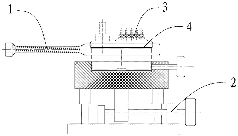
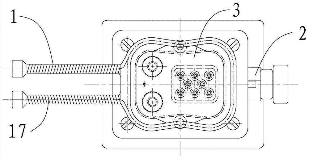
[0027] refer to Figure 1-2 As shown, the sealing contactor removal device of the present invention ...


PUM


Abstract

The invention discloses a sealing contactor disassembly device which comprises a radio-frequency induction coil and a disassembly jig. The radio-frequency induction coil is located above the disassembly jig and used for generating heat to melt solder of a sealing contactor, and the disassembly jig is used for clamping and adjusting the sealing contactor to make the sealing contactor correspond to the radio-frequency induction coil in position. According to the sealing contactor disassembly device, the radio-frequency induction coil is used in cooperation with the disassembly jig, molecular movement inside a weldment is stimulated based on the high-frequency induction principle, the heat is generated from the inside of metal to melt the tin-lead solder and disassemble the sealing contactor, the heat-affected area of heating and melting is small, the product to be disassembled does not need to be shaken or vibrated, and therefore the product can be effectively prevented from being deformed and damaged; meanwhile, labor intensity is greatly reduced for operators, and operation is safer.

Description

technical field [0001] The invention relates to the technical field of manufacturing and assembling a sealing contactor, in particular to a disassembling device for a sealing contactor. Background technique [0002] With the rapid development and progress of various technical fields in the electromechanical industry, the technical specifications of circuit breakers and contactors for power switching in various power control systems are also getting higher and higher. The original high current, high voltage Unsealed circuit breakers and contactors can no longer meet the requirements of use, so various sealed circuit breakers and contactors are widely used in various electromechanical industries due to their superior performance, and their use in aviation and aerospace shows their unique superiority. [0003] All parts and components in the contact seat plate components of various sealed circuit breakers and contactors are sealed with molten tin-lead solder. In the assembly ...

Claims


Application Information

Patent Timeline
IPC IPC(8): B23P19/00
CPCB23K1/018B23K3/00B23K3/0475
Inventor 阳毕锋
Owner GUIZHOU TIANYI ELECTRICAL
Learn More