
Distortion calibration device and method for f-theta optical system

An optical system and a calibrated technology, applied in the field of optical testing, can solve the problems of low measurement accuracy, errors in processing and assembly, and complex target production, and achieve the effects of high measurement accuracy and high work efficiency.

Inactive Publication Date: 2014-01-08
XI'AN INST OF OPTICS & FINE MECHANICS - CHINESE ACAD OF SCI
View PDF13 Cites 11 Cited by
  • Summary
  • Abstract
  • Description
  • Claims
  • Application Information

AI Technical Summary

Problems solved by technology

Although the distortion does not affect the image clarity, the distortion of the optical system directly affects the geometric position accuracy of the imaging. The larger the field of view, the greater the distortion
In order to obtain accurate geometric position images, although the optical system is designed to correct the distortion of different fields of view as much as possible, errors will inevitably occur due to processing and assembly, resulting in a large deviation between the final optical system and the design results. It is required to accurately measure the distortion of the optical system, try to find out the actual distortion error distribution of the optical system, and correct it by mathematical methods if necessary, so as to achieve the purpose of improving accuracy
At present, there is no special device or method for distortion calibration of f-theta optical system. Occasionally, it is reported that a specially made target is used for qualitative verification. This method has many disadvantages: different types of f-theta optical system need to design different targets, Unable to achieve universality; even if the same f-θ optical system is under different object distance conditions, the target size is different; the target production is more complicated; the measurement accuracy is low, affected by the target production and calibration, the final distortion calibration accuracy is 100% One or so; the target is a flat figure, which cannot provide a real curved surface effect

Method used


Image

  • Distortion calibration device and method for f-theta optical system
  • Distortion calibration device and method for f-theta optical system
  • Distortion calibration device and method for f-theta optical system

Examples


Embodiment Construction

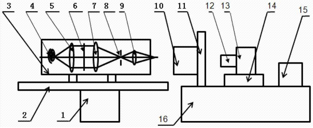
[0030] The present invention is a kind of distortion testing device of f-theta optical system, including turntable 1, long guide rail 2, composed of light source 4, collimator mirror 5, optical filter 6, condenser mirror 7, star hole plate 8, target miniature mirror 9 Target generator, special tooling 11, image analyzer made up of imaging objective lens 12, detector 13, three-dimensional mobile support 14, computer 15, platform 16, computer 15 includes automatic control software, calculation processing software; target generator setting On the object side of the calibrated optical system, the image analyzer is set on the image side of the calibrated optical system, and the moving parts are connected with the computer, and their movement is controlled by automatic control software.

[0031] The function of the turntable 1 is to drive the target generator to rotate, and provide the target of the off-axis field of view for the f-θ optical system, which can be an electronically con...


PUM


Abstract

The invention provides a distortion testing device for an f-theta optical system. The testing device comprises a turntable, a guide rail, a target generator and an image analyzer in sequential arrangement, wherein the guide rail is arranged on the turntable, the target generator is arranged at the object space of a calibrated optical system, and the image analyzer is arranged at the image space of the calibrated optical system. The distortion calibration device and a distortion calibration method for the f-theta optical system have the advantage that the providing of targets in different object distances can be simultaneously realized.

Description

technical field [0001] The invention belongs to the field of optical testing, and relates to a device and method for calibrating f-theta optical system distortion, in particular to a calibrating optical system distortion for an f-theta structured optical camera before docking with a detector. Background technique [0002] The f-θ optical system is commonly known as a fisheye lens, and its field of view can reach more than 180 degrees. Its special application in photography is well known. However, the use of fisheye lenses is far more than that. They are also very useful in astronomy, meteorology, movies, surveying, pipeline inspection, fire monitoring, medical endoscopic inspection, and even public security and frontier defense. In today's information age, fisheye lenses have been successfully applied in navigation, positioning, remote sensing, optical communication, machine vision, tiny intelligent systems and other fields; and in national defense and military affairs, they...

Claims


Application Information

Patent Timeline
Patent Type & Authority Applications(China)
IPC IPC(8): G01M11/02G01M11/04
Inventor 周艳赵建科张洁徐亮昌明刘峰胡丹丹
Owner XI'AN INST OF OPTICS & FINE MECHANICS - CHINESE ACAD OF SCI
Learn More