A driving device for a moving platform and its working method

A technology of driving device and working method, which is applied in printing, rotary printing machine, printing machine, etc., can solve the problems of working speed increase limitation, occupying space, and complex transmission relationship of the device, so as to save transmission links, simplify structure, and improve applicability wide effect

Active Publication Date: 2017-05-31
MASTERWORK GROUP CO LTD
View PDF5 Cites 0 Cited by
  • Summary
  • Abstract
  • Description
  • Claims
  • Application Information

AI Technical Summary

Problems solved by technology

[0006] The driving device in the prior art relies on the flywheel to drive the platform to punch. When the working speed is low, due to the small flywheel at low speed, the stamping cannot pass through, resulting in a stuffy car.
In addition, this kind of driving device adopts the transmission mode of worm gear. Due to the large reduction ratio of the worm gear, when the speed of the motor is increased, and then divided by the higher reduction ratio, the working speed of the platform can be limited. The increase in speed is greatly reduced, and the mechanical transmission efficiency of the worm gear is also low, so the increase in working speed using this driving device is limited
At present, the high-speed printing equipment is an industry trend, and the limited increase in the working speed of the host will inevitably restrict the overall operating speed of the equipment.
At the same time, the complex transmission relationship of this device occupies a huge space.

Method used


Image

  • A driving device for a moving platform and its working method
  • A driving device for a moving platform and its working method
  • A driving device for a moving platform and its working method

Examples


Embodiment

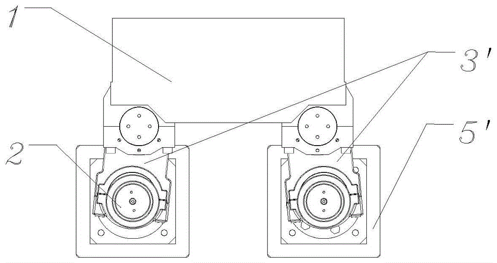
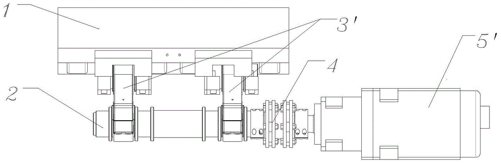
[0026] Embodiment: a kind of moving platform driving device (see figure 2 , image 3 ), characterized in that it consists of a moving platform 1, a connecting rod 3', an eccentric shaft 2, a coupling 4 and a servo control system 5'; the servo control system 5' is connected to the eccentric shaft 2 through a coupling 4, The eccentric shaft 2 is connected with the connecting rod 3' through a rotating pair, and the connecting rod 3' is connected with the moving platform 1 through a rotating pair.

[0027] The connecting rod 3' is connected to a symmetrical position relative to the center plane of the moving platform 1, so that the moving platform can be placed stably; every two connecting rods 3' are connected to an eccentric shaft 2; each eccentric shaft 2 is connected to a set of servo Control system 5' and coupling 4. (See figure 2 , image 3 )

[0028] There are four connecting rods 3', and the four connecting rods 3' are arranged symmetrically with respect to the cent...


PUM


Abstract

Provided is a device for driving a movable platform. The device for driving the movable platform is characterized by comprising the movable platform, connecting rods, eccentric shafts, couplers and servo control systems, wherein the servo control systems are connected with the eccentric shafts through the couplers, the eccentric shafts are connected with the connecting rods through revolute pairs, and the connecting rods are connected with the movable platform through revolute pairs. The working method of the device for driving the movable platform comprises the steps that the servo control system drives the eccentric shafts to rotate through the couplers, the connecting rods which are connected with the eccentric shafts vertically move along with the eccentric shafts; the connecting rods drive the movable platform to vertically move through coordination control of the servo control systems. The device for driving the movable platform and the working method of the device for driving the movable platform have the advantages that shaft transmission is abandoned, transmission links are omitted, the structure is simplified and compact; space is saved, the requirement for a high speed of a whole machine can be met, and corresponding motions can be accomplished more accurately; the influence caused by a flywheel track does not exist and the phenomena such as sudden shut-down cannot happen in the condition of low speed; due to the fact that servo is used for directly driving a main machine, more flexibility is achieved, and applicability is better.

Description

[0001] (1) Technical fields: [0002] The invention is suitable for printing machinery, especially a driving device for a moving platform and a working method thereof. [0003] (2) Background technology: [0004] In printing machinery, especially in die-cutting or bronzing equipment of flat-pressing mode of post-press equipment, a moving platform and a static platform are generally set in the host part, and auxiliary tools are set according to the needs of the process, such as die Cut version, hot stamping version, etc. The realization of the die-cutting or hot-stamping process is completed by driving the moving platform to press regularly towards the static platform through the driving device. [0005] In the prior art, the moving platform driving device widely used in post-press equipment such as figure 1 shown. Its transmission route is main motor 5—transmission device 8—flywheel 9—coupling 4—worm 6—worm wheel 7—eccentric shaft 2—connecting rod assembly 3—moving platform ...

Claims


Application Information

Patent Timeline
Patent Type & Authority Patents(China)
IPC IPC(8): B41F13/008
Inventor 王玉信彭章波
Owner MASTERWORK GROUP CO LTD
Why Eureka
Try Eureka