Mechanical mixing stirrer

A mechanical mixing and agitator technology, applied in the direction of mixers, mixer accessories, mixers with rotating agitation devices, etc., can solve the problems of complex design and manufacturing, many consumables, and large energy consumption for mixing, and achieve low maintenance costs. Create flexible, power-efficient effects

A mechanical mixing and agitator technology, applied in the direction of mixers, mixer accessories, mixers with rotating agitation devices, etc., can solve the problems of complex design and manufacturing, many consumables, and large energy consumption for mixing, and achieve low maintenance costs. Create flexible, power-efficient effects

CN103521110AActive Publication Date: 2014-01-22HUATIAN ENG & TECH CORP MCC

Image

  • Mechanical mixing stirrer

Examples


Embodiment Construction

[0016] The present invention will be further described below in conjunction with the accompanying drawings.

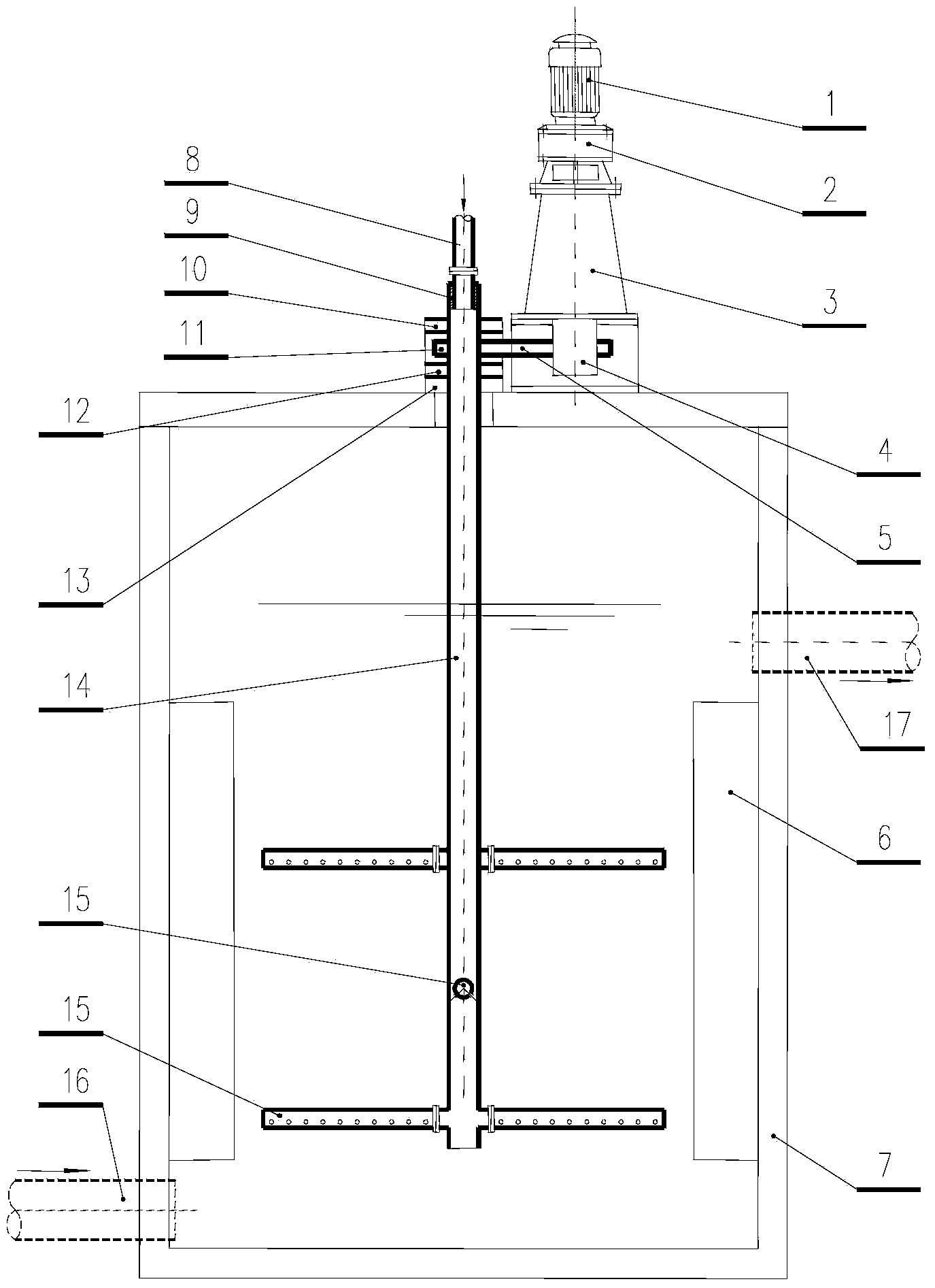
[0017] The mechanical mixing agitator of the present invention, the agitator is arranged in the mixing tank, is characterized in that: the agitator includes a driving mechanism, the agitating shaft driven by the driving mechanism through the transmission mechanism, wherein the agitating shaft is a hollow structure, The stirring shaft is connected with the medicine feeding pipe, and several strip-shaped porous pipes are interposed on the stirring shaft, and the stirring shaft is connected with the porous pipe.

[0018] Such as figure 1 As shown, the mechanical mixing agitator of this embodiment is arranged in a mixing tank, and the mixing tank is respectively provided with an inlet pipe 16 and an outlet pipe 17, and a deflector 6 is arranged in the mixing tank. Described agitator comprises driving mechanism, the stirring shaft 14 that described driving mechanism drives...


PUM

PropertyMeasurementUnit
Diameteraaaaaaaaaa

Abstract

The invention discloses a mechanical mixing stirrer, and mainly aims to provide the mechanical mixing stirrer having the advantages of high mixing uniformity degree, reliable operation, and convenient construction and installation. The mechanical mixing stirrer comprises a drive mechanism; the drive mechanism drives a stirring shaft through a transmission mechanism; the stirring shaft is of a hollow structure, is connected with a drug feeding pipe, is insertedly provided with a plurality of strip-shaped porous pipes at intervals, and is communicated with the porous pipes. The mechanical mixing stirrer enables a drug liquid to be mixed uniformly, has the advantages of decreased drug using amount, simple manufacture, flexible manufacture, and low maintenance cost, and saves power consumption.

Description

technical field [0001] The invention relates to a mechanical mixing agitator. Background technique [0002] At present, in the mixing system of water supply and drainage treatment, the methods used can be divided into hydraulic mixing and mechanical mixing. 1) Hydraulic mixing. Hydraulic mixing includes water pump mixing, tubular static mixer mixing, diffusion mixer mixing, falling water mixing and hydraulic jump mixing. Water pump mixing is to add liquid medicine to the suction pipe of the incoming water pump, and achieve the purpose of mixing through the high-speed rotation of the pump impeller. The tubular static mixer is to set a section of multi-section fixed blades in the water pipe, so that the water flow can generate vortex and cross flow in it to achieve the purpose of mixing. The diffusion mixer is to add a conical dispensing cap in front of the orifice mixer, and use the vortex and reverse flow formed by the orifice mixer to achieve the purpose of mixing. Wate...

Claims


Application Information

Patent Timeline
22 Jan 2014
Publication
CN103521110A
IPC
B01F7/18; B01F15/02
Inventors
李旭