Drive system for synchronous motor
A synchronous motor and drive system technology, which is applied in the estimation/correction of motor parameters, motor generator control, AC motor control, etc., to achieve the effect of increasing the number of switches
- Summary
- Abstract
- Description
- Claims
- Application Information
AI Technical Summary
Problems solved by technology
Method used
Image

Examples
no. 1 approach )
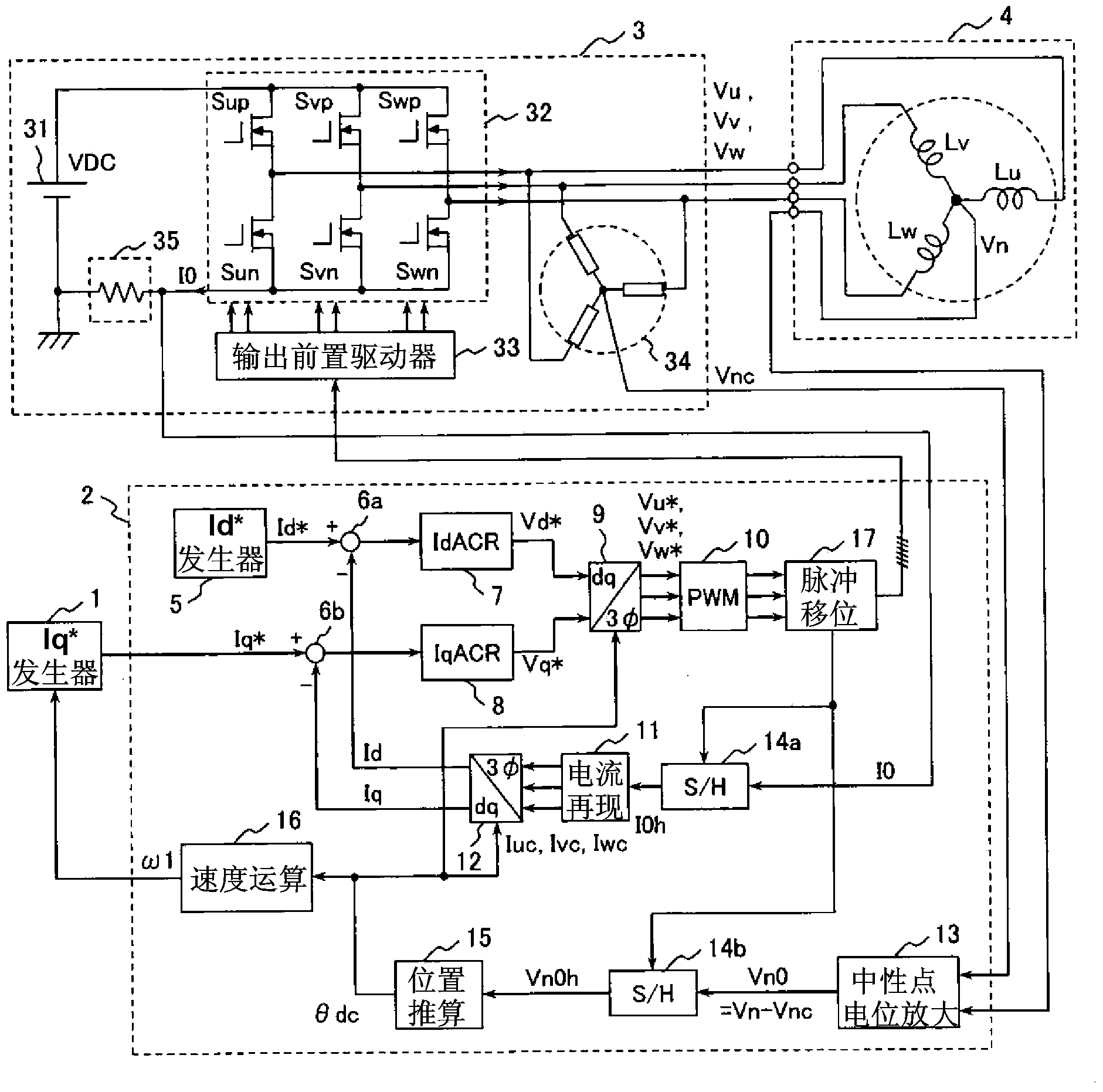
[0066] figure 1 It is a block diagram showing the configuration of the motor drive system according to the first embodiment of the present invention.
[0067] The purpose of this motor drive system is to drive a permanent magnet motor (three-phase synchronous motor) 4 . Roughly, the motor drive system includes an Iq* generator 1, a controller 2, an inverter 3, and a permanent magnet motor 4 as a driving object, wherein the inverter 3 includes an inverter main circuit 32 and a single current (one-shunt) detector 35 .
[0068] The Iq* generator 1 is a circuit that generates a current command Iq* corresponding to the torque of the motor. The Iq* generator 1 is a superordinate controller to the controller 2 . Usually, the configuration is such that the necessary current command Iq* is generated while observing the actual speed ω1 in order to make the number of revolutions of the permanent magnet motor 4 a predetermined speed. The current command Iq* which is the output of the...
no. 2 approach )
[0123] Next, a second embodiment of the present invention will be described.
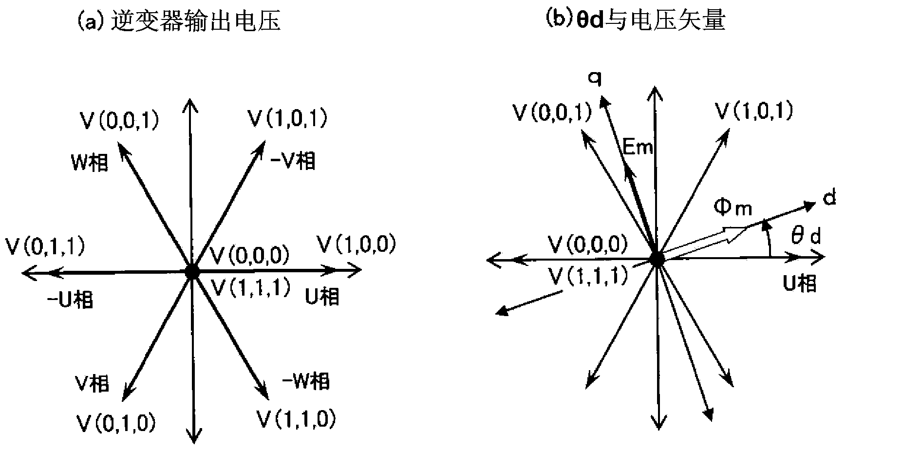
[0124] In the first embodiment, in order to detect Vn0, by introducing the pulse shifter 17 and shifting the PWM pulse wave, the output period of the voltage vector other than the zero vector can be extended, and two types of voltage vectors not included in the original PWM waveform can be newly output. vector, thereby improving the position estimation accuracy.
[0125] In the example of the first embodiment, V(1, 1, 0), V(0, 1, 0). here, from figure 2(a) It can be known that V(0, 0, 1) and V(1, 1, 0) and V(1, 0, 1) and V(0, 1, 0) are vectors in opposite directions respectively. Not only adding the vector in the opposite direction like this, but also adding the voltage vector in the direction not included in the PWM before the pulse shift, such as V (1, 0, 0), produces the effect of exploring the rotor position and can further improve the rotor position. the precision of the information. For ...
no. 3 approach )
[0129] Then for the third embodiment of the present invention, use Figure 7 Be explained.
[0130] In the first and second embodiments, it is shown that the voltage vectors applied to the motor can be increased from two to three or four by introducing the pulse shifter 17 . In these embodiments, all three phases are switched at the same frequency as the triangular wave carrier. In contrast, in the third embodiment, an example in which the switching frequencies of three phases are different (two-phase switching) will be described.
[0131] Figure 7 (a) shows a two-phase switching method using a triangular wave carrier. can be known with Figure 4 Differently, the three-phase voltage commands Vu*, Vv*, Vw* are close to the upper peak of the triangular wave carrier. In this example, Vw* of the maximum value among the three-phase voltage commands coincides with the peak value of the upper wave of the triangular wave carrier. In this way, by setting the same offset value fo...
PUM
 Abstract
Description
Claims
Application Information
 - Generate Ideas
- Intellectual Property
- Life Sciences
- Materials
- Tech Scout
- Unparalleled Data Quality
- Higher Quality Content
- 60% Fewer Hallucinations
Browse by: Latest US Patents, China's latest patents, Technical Efficacy Thesaurus, Application Domain, Technology Topic, Popular Technical Reports.
© 2025 PatSnap. All rights reserved.Legal|Privacy policy|Modern Slavery Act Transparency Statement|Sitemap|About US| Contact US: help@patsnap.com