Gear combined type variable-speed transmission device

A variable speed transmission and combined technology, which is applied in the field of synchronizers, gear combined variable speed transmissions, and clutches, can solve the problems of complex structure and control system, difficult parts processing and manufacturing, and achieve simplified control methods and control links, saving axial space and radial space, simple control and maintenance

Inactive Publication Date: 2014-01-29
郭质刚
View PDF6 Cites 2 Cited by
  • Summary
  • Abstract
  • Description
  • Claims
  • Application Information

AI Technical Summary

Problems solved by technology

The electro-hydraulic automatic transmission (AT) has a series of planetary gear trains and multiple clutches and brakes, which can automatically shift gears through electronically controlled hydraulic drive, but the structure and control system are complicated, the transmission efficiency is low, and the parts are difficult to process Large, high manufacturing and maintenance costs
The mechanical continuously variable transmission (CVT) can realize continuous stepless speed regulation, but the transmission torque is small, the processing and manufacturing precision of the parts is high, and the manufacturing is difficult. Because of its inherent friction transmission characteristics, the transmission efficiency is low, but due to the stepless speed change The advantages of better matching between transmission and engine make up for the disadvantages of friction transmission
The dual-clutch transmission (DSG) has the advantages of simple structure, high transmission efficiency, rapid and smooth shifting of uninterrupted power, etc., but the coaxial dual clutch with single input and double output has complex structure, difficult control and high manufacturing precision due to its structural characteristics. , the axial length is too long, the speed ratio of each pair of gears is too large, resulting in large radial dimensions, the number of gears available is small, and the number of gears is too large when the number of gears is provided.
[0003] The currently used transmission reverse gear mechanism has the disadvantages of many parts, large structure size and high cost

Method used


Image

  • Gear combined type variable-speed transmission device
  • Gear combined type variable-speed transmission device
  • Gear combined type variable-speed transmission device

Examples


Embodiment Construction

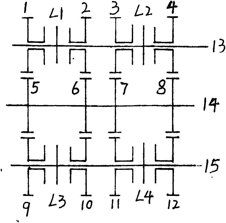
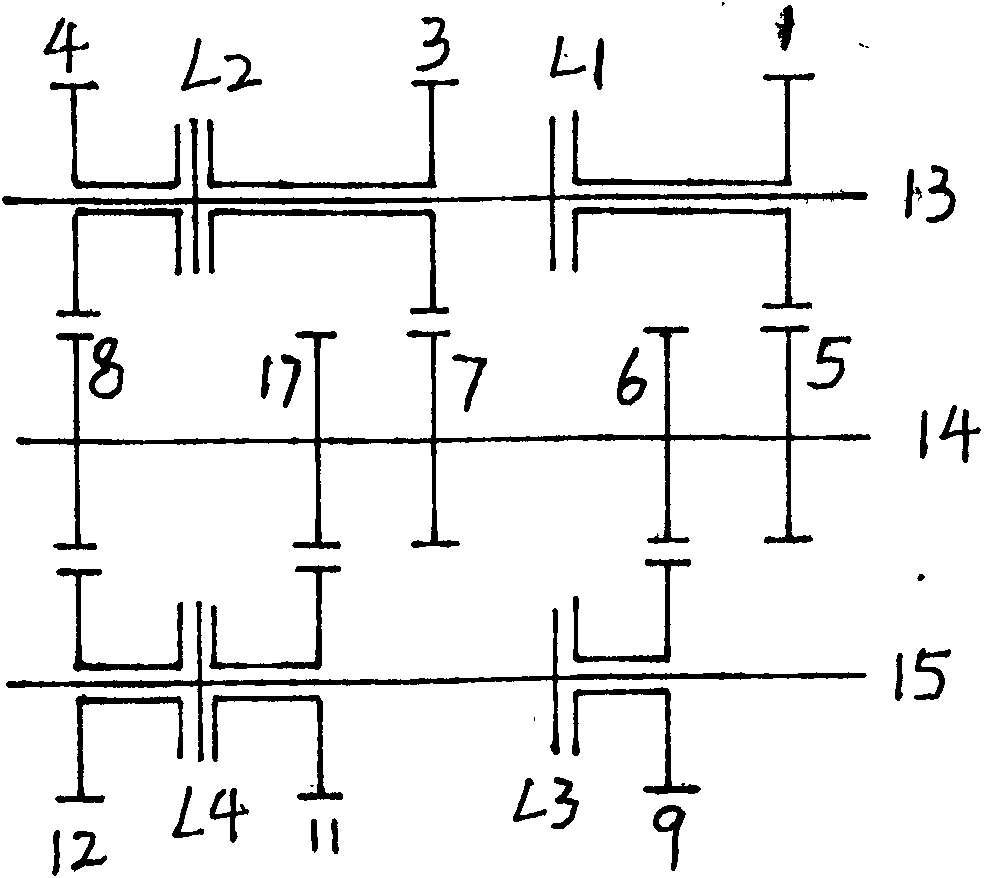
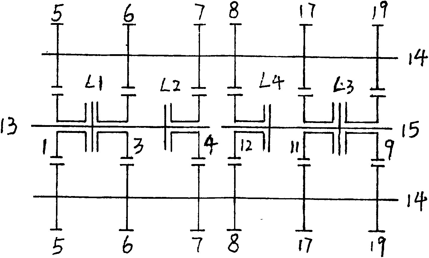
[0022] Such as figure 2Shown, the input shaft (13), output shaft (15) and intermediate shaft (14) and reverse gear shaft (not shown in the figure) arranged in parallel, are rigidly connected with gear (5) (6) on the intermediate shaft (14). )(7)(8)(17), three gears (1)(3)(4) that can rotate freely around its axis are arranged on the input shaft (13), and there are three gears (1)(3)(4) that can freely rotate around its axis on the output shaft (15). The three gears (9) (11) (12) that rotate, the gears (4) (12) mesh with the gear (8) on the intermediate shaft (14) respectively, and the gear (3) meshes with the upper gear (7) on the intermediate shaft (14). ), the gear (1) meshes with the gear (5) on the countershaft (14), the gear (11) meshes with the gear (17) on the countershaft (14), and the gear (9) meshes with the gear (14) on the countershaft (14) 6) meshing, there is a double clutch (L2) between the upper gear (3) (4) of the input shaft (13), the upper gear (1) of the ...


PUM


Abstract

The invention relates to a gear combined type variable-speed transmission device. The gear combined type variable-speed transmission device consists of an input shaft, an output shaft, an intermediate shaft, clutches (or synchronizers) and gears. More than 6 clutches or one clutch and more than 6 synchronizers and more than 9 gears are combined in serial-parallel connection modes, the gear number is remarkably increased, and the number of shifting gears is decreased. Due to the fact that each pair of gears has small speed ratio and adopts a short transmission shaft structure, the rigidity of a transmission is improved, the radial and axial sizes are reduced, and the transmission is compact in structure and high in mechanical efficiency. The invention further provides a reverse gear device used on a mechanical variable-speed transmission mechanism.

Description

technical field [0001] The invention relates to a mechanical speed change transmission device, in particular to a combined speed change transmission device of a clutch, a synchronizer and a gear. Background technique [0002] Currently, there are three main types of automatic transmissions used in automobiles: hydraulic automatic transmission (AT), electromechanical automatic transmission (AMT) and mechanical continuously variable automatic transmission (CVT). In the field of electronically controlled mechanical automatic transmission, there is also a variable speed transmission method, that is, dual-clutch automatic transmission (DSG). The mechanical automatic transmission (AMT) is based on the manual transmission, and an automatic control device is added to control the clutch and select the gear pair on the fixed shaft system for automatic gear shifting. The electro-hydraulic automatic transmission (AT) has a series of planetary gear trains and multiple clutches and brake...

Claims


Application Information

Patent Timeline
Patent Type & Authority Applications(China)
IPC IPC(8): F16H57/023F16H61/688F16H3/78
CPCF16H3/78F16H57/02F16H57/023F16H2057/02086F16H2057/02095F16H2200/0078F16H2200/2041F16H2200/2043
Inventor 郭质刚
Owner 郭质刚
Why Eureka
Try Eureka