
Control device for automatic underwater welding repair equipment

A technology for maintenance equipment and control devices, applied in welding equipment, arc welding equipment, fluid pressure actuation devices, etc., can solve problems such as low efficiency, difficult component control, and high manufacturing costs, so as to improve quality and work efficiency, realize The effect of remote automatic control and low cost of on-site operation

Active Publication Date: 2014-02-05
STATE NUCLEAR POWER PLANT SERVICE
View PDF6 Cites 3 Cited by
  • Summary
  • Abstract
  • Description
  • Claims
  • Application Information

AI Technical Summary

Problems solved by technology

[0003] The safety end weld of the reactor pressure vessel is an important part of the pressure boundary of the circuit. Its composition is complex, and it is fused by five alloys, so it is difficult to control the composition; Under the impact of water flow, the inner wall is very prone to corrosion damage, and there are current cases showing that the weld is a high-incidence part of nuclear power plant pressure vessel damage
[0004] At present, the repair welding and surfacing welding of the inner wall of the safety end of the pipe are usually carried out by divers entering the water. This maintenance method is inefficient, and the quality of the repair is difficult to guarantee, and the high radioactivity in the environment seriously endangers the health of the workers.
For the repair of the weld, foreign nuclear power operation service providers have carried out a lot of technical research and developed professional maintenance equipment and control devices. The stability requirements are extremely high, so the control system is complex and the manufacturing cost is relatively high

Method used


Image

  • Control device for automatic underwater welding repair equipment
  • Control device for automatic underwater welding repair equipment
  • Control device for automatic underwater welding repair equipment

Examples


Embodiment Construction

[0098] The implementation of the present invention will be illustrated by specific specific examples below, and those skilled in the art can easily understand other advantages and effects of the present invention from the contents disclosed in this specification.

[0099] It should be noted that the structures, proportions, sizes, etc. shown in the drawings attached to this specification are only used to match the content disclosed in the specification, for those who are familiar with this technology to understand and read, and are not used to limit the implementation of the present invention. Limiting conditions, so there is no technical substantive meaning, any modification of structure, change of proportional relationship or adjustment of size, without affecting the effect and purpose of the present invention, should still fall within the scope of the present invention. The disclosed technical content must be within the scope covered. At the same time, terms such as "upper"...


PUM


Abstract

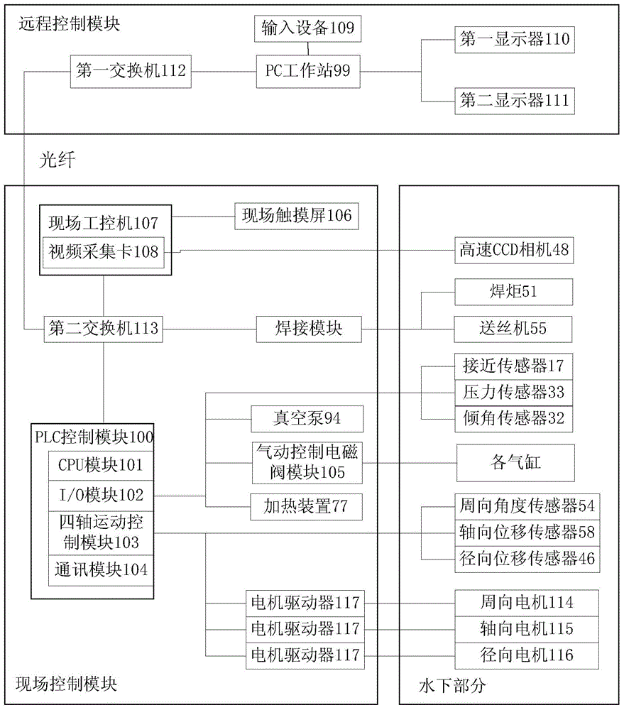
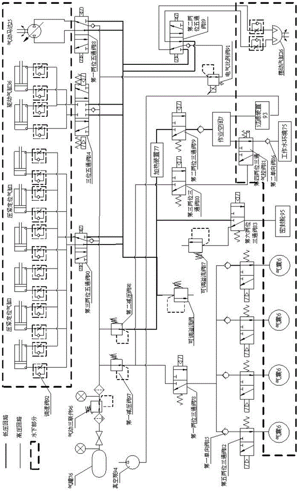
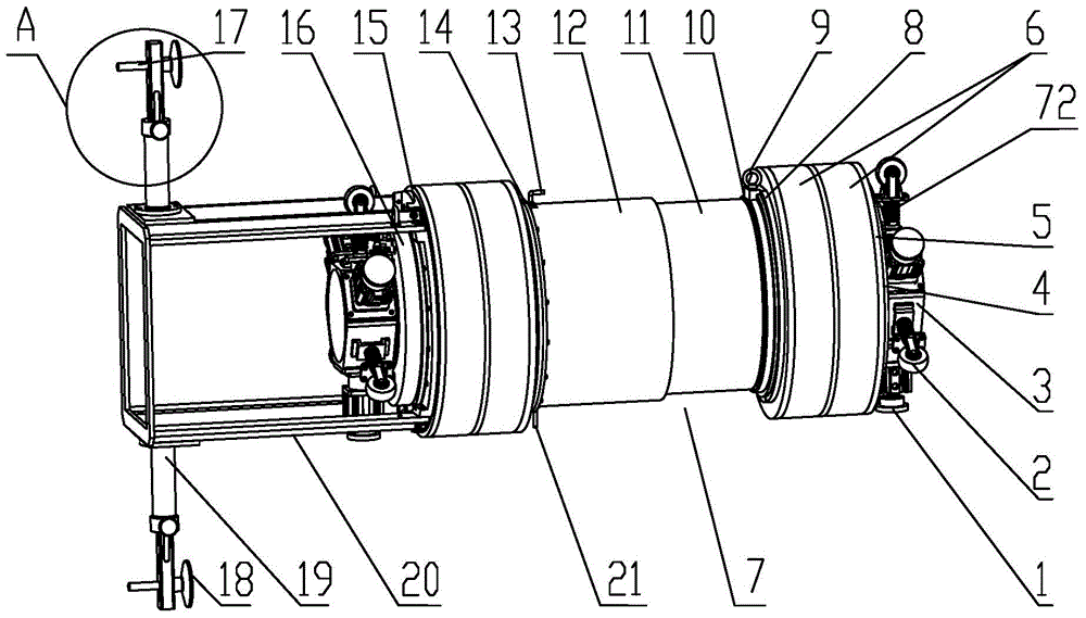
The invention provides a control device for automatic underwater welding repair equipment. The control device comprises a spindle, gasbag supports, gasbags, a working space, an axially movable cylinder, a gas inlet pipe and a drain pipe which are arranged on the cylinder, and a welding device arranged on the cylinder, and also comprises a gas tank respectively connected with first, second and third two-position three-way valves, a driving cylinder connected with the gas tank through a three-position five-through valve, and a PC (Personal Computer) workstation connected with a PLC (Programmable logic controller) control module, wherein the first two-position three-way valve is connected with the gasbags, and the second two-position three-way valve is connected with the working space through the gas inlet pipe; the third two-position three-way valve is connected with a two-position three-way gas control valve arranged on the drain pipe, and the PLC control module is respectively connected with the first, second and third two-position three-way valves and the three-position five-through valve. According to the control device, for the automatic underwater welding repair equipment, a local dry repair environment can created, and the control device is safe and reliable, is convenient to control, and is relatively lower in field operation cost.

Description

technical field [0001] The invention relates to the field of equipment control, in particular to an underwater automatic welding maintenance equipment control device. Background technique [0002] In recent years, in the maintenance of nuclear power plant reactor pressure vessels, in order to reduce the damage of radiation to maintenance workers, maintenance work with water is often adopted, that is, the pressure vessel is filled with water to shield the gamma rays that are extremely harmful to the human body. . However, underwater maintenance operations put forward higher requirements for technology, and usually require the development of dedicated automated maintenance equipment. At the same time, this kind of maintenance equipment not only needs to meet the requirements of the operation function, but also its volume and motion trajectory must be designed according to the actual working space, and it also needs to have the functions of waterproof and radiation protection,...

Claims


Application Information

Patent Timeline
IPC IPC(8): B23K9/04B23K9/32
CPCB23K9/048B23K9/12B23K9/323B23K9/328B23K2101/12B24B9/04F15B13/06F15B21/02
Inventor 文忠程保良李颖俞照辉闫国华张凯峰叶琛
Owner STATE NUCLEAR POWER PLANT SERVICE
Learn More