
Piezoresistive integrated three-dimensional turning force sensor

A sensor, turning force technology, applied in the measurement of the property force of piezoresistive materials, the measurement of force components, metal processing mechanical parts, etc. The problem is not high, to achieve the effect of improving measurement accuracy and sensitivity, reducing mutual influence and coupling

Active Publication Date: 2014-02-05
XIAN WINWAY TOOLS
View PDF7 Cites 12 Cited by
  • Summary
  • Abstract
  • Description
  • Claims
  • Application Information

AI Technical Summary

Problems solved by technology

[0003] Traditional turning force dynamometers mainly include resistance strain type, piezoelectric type, current type, optical fiber type, capacitive type, etc., but there is a contradiction between sensitivity and stiffness in resistance strain type dynamometers; The static force cannot be tested due to leakage, the increase of the natural frequency is limited by the contact stiffness of the assembly, the maintenance is extremely inconvenient, and the price is expensive; the measurement accuracy of the current type dynamometer is not high, and due to the current hysteresis, it cannot meet the comparative requirements for real-time monitoring of the turning force. High requirements; fiber optic and capacitive sensors are susceptible to external vibration and temperature changes and cannot be measured accurately

Method used


Image

  • Piezoresistive integrated three-dimensional turning force sensor
  • Piezoresistive integrated three-dimensional turning force sensor
  • Piezoresistive integrated three-dimensional turning force sensor

Examples


Embodiment Construction

[0017] The present invention will be described in further detail below in conjunction with the accompanying drawings.

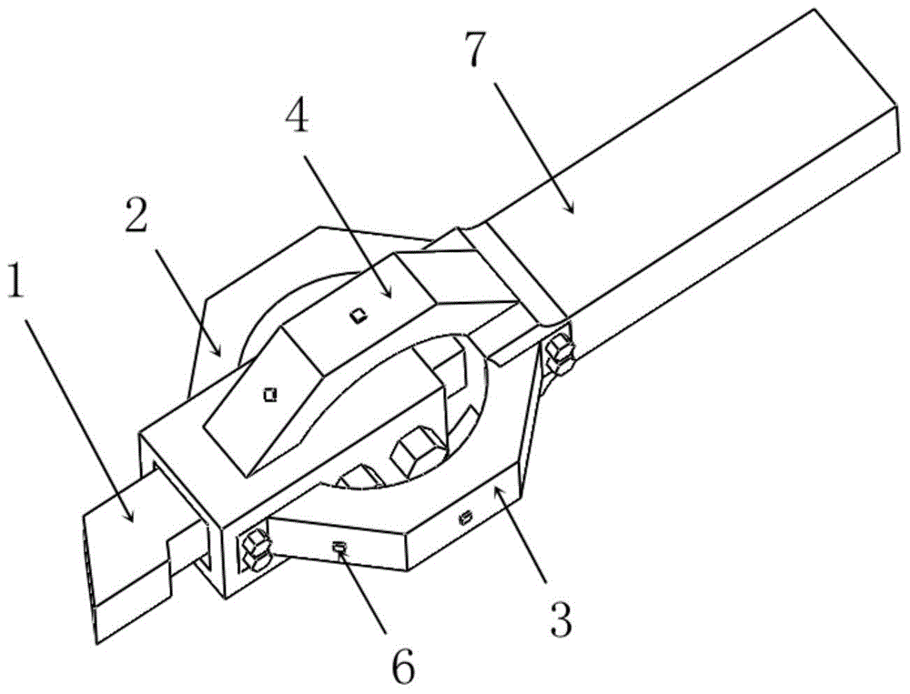
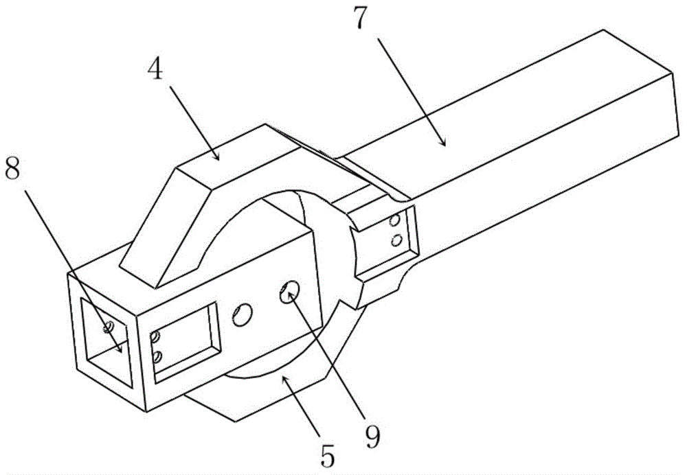
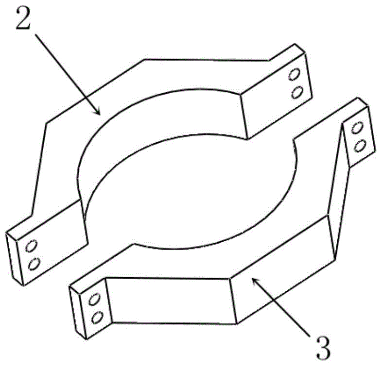
[0018] refer to figure 1 , figure 2 with image 3 , a piezoresistive integrated three-dimensional turning force sensor, including a sensor main structure 7, a turning tool 1 is installed in the head turning tool slot 8 of the sensor main structure 7, and the turning tool 1 is fixed by bolts, and the sensor main structure 7 The first vertical octagonal half-ring 4 and the second vertical octagonal half-ring 5 are respectively arranged on the upper and lower sides of the middle part, the first vertical octagonal half-ring 4 and the second vertical octagonal half-ring 5 form a vertical octagonal ring, as a vertical The elastic body structure of the direction; the front and rear sides of the middle part of the sensor main body structure 7 are respectively connected to the first horizontal octagonal half ring 2 and the second horizontal octagonal half ring 3, a...


PUM


Abstract

The invention relates to a piezoresistive integrated three-dimensional turning force sensor. A turning tool is installed in a head turning tool slot of a sensor main structure, a first vertical octagonal semi-ring and a second vertical octagonal semi-ring are arranged on an upper surface and a lower surface of a middle portion of the sensor main structure respectively, a front side and a rear side of the middle portion of the sensor major structure are connected with a first horizontal octagonal semi-ring and a second horizontal octagonal semi-ring respectively, a tail portion of the sensor major structure is provided with a sensor handle, and a micro-electromechanical system (MEMS) silicon micro force sensor chip is packaged on an outer surface of the octagonal semi-ring. According to the piezoresistive integrated three-dimensional turning force sensor, two octagonal ring structures which are perpendicular to each other are used so that independent measurement of three-dimensional turning forces is achieved, and interaction influence and coupling among effective lateral forces are reduced; the MEMS silicon micro force sensor chip is used, so that measurement accuracy and sensitivity of the chip are greatly improved, and measurement of stress and stain can be achieved by only packaging the MEMS silicon micro force sensor chip in one place; accurate measurement of three-dimensional turning forces is achieved, and both dynamic forces and static forces can be measured.

Description

technical field [0001] The invention relates to the technical field of intelligent manufacturing equipment, in particular to a piezoresistive integrated three-dimensional turning force sensor. Background technique [0002] In metal cutting, turning is one of the most common processing methods. Turning force is an important index to reflect the turning process. The magnitude of the turning force is closely related to the change of the turning process. Every small change in the turning state can be reflected by the change of the turning force. Turning force is closely related to tool wear, machining accuracy, turning temperature, power consumption, etc. Therefore, how to accurately measure turning force is very important to improve machining performance. [0003] Traditional turning force dynamometers mainly include resistance strain type, piezoelectric type, current type, optical fiber type, capacitive type, etc., but there is a contradiction between sensitivity and stiffnes...

Claims


Application Information

Patent Timeline
IPC IPC(8): B23Q17/09G01L1/18G01L5/16
CPCB23Q17/0966
Inventor 赵玉龙赵友
Owner XIAN WINWAY TOOLS
Learn More