Biomechanical generator

A biomechanical and generator technology, applied in the directions of biochemical cleaning devices, biochemical equipment and methods, enzymology/microbiology devices, etc. Observation and research of endplate chondrocytes and other issues

Inactive Publication Date: 2014-02-05
王卫明 +2
View PDF2 Cites 8 Cited by
  • Summary
  • Abstract
  • Description
  • Claims
  • Application Information

AI Technical Summary

Problems solved by technology

[0002] With the continuous development of medicine, especially the development of orthopedics, the cross-fusion between it and biomechanics is getting closer and closer. In the field of orthopedics, the degeneration of the spine and its intervertebral disc is a common disease, but currently The direction of research is mainly focused on the model of spine and intervertebral disc degeneration caused by mechanical stimulation on living animals, and then through cytology, molecular biology, immunology detection and analysis to study the mechanism of degeneration, such research in the cytology stage It is a static research, which is to analyze the morphology and cytoskeleton of the cells in the end state of stress. At present, there is no device that can completely simulate the dynamic stress and compound stress state of the normal human spine and intervertebral disc, which makes it impossible to observe under dynamic conditions. The changes in the general shape, microstructure, cytoskeleton, and biological migration of cells under the action of constant mechanical stimulation make it impossible to observe and study the dynamic stress and composite stress state of vertebral endplate chondrocytes

Method used


Image

  • Biomechanical generator
  • Biomechanical generator
  • Biomechanical generator

Examples


Embodiment Construction

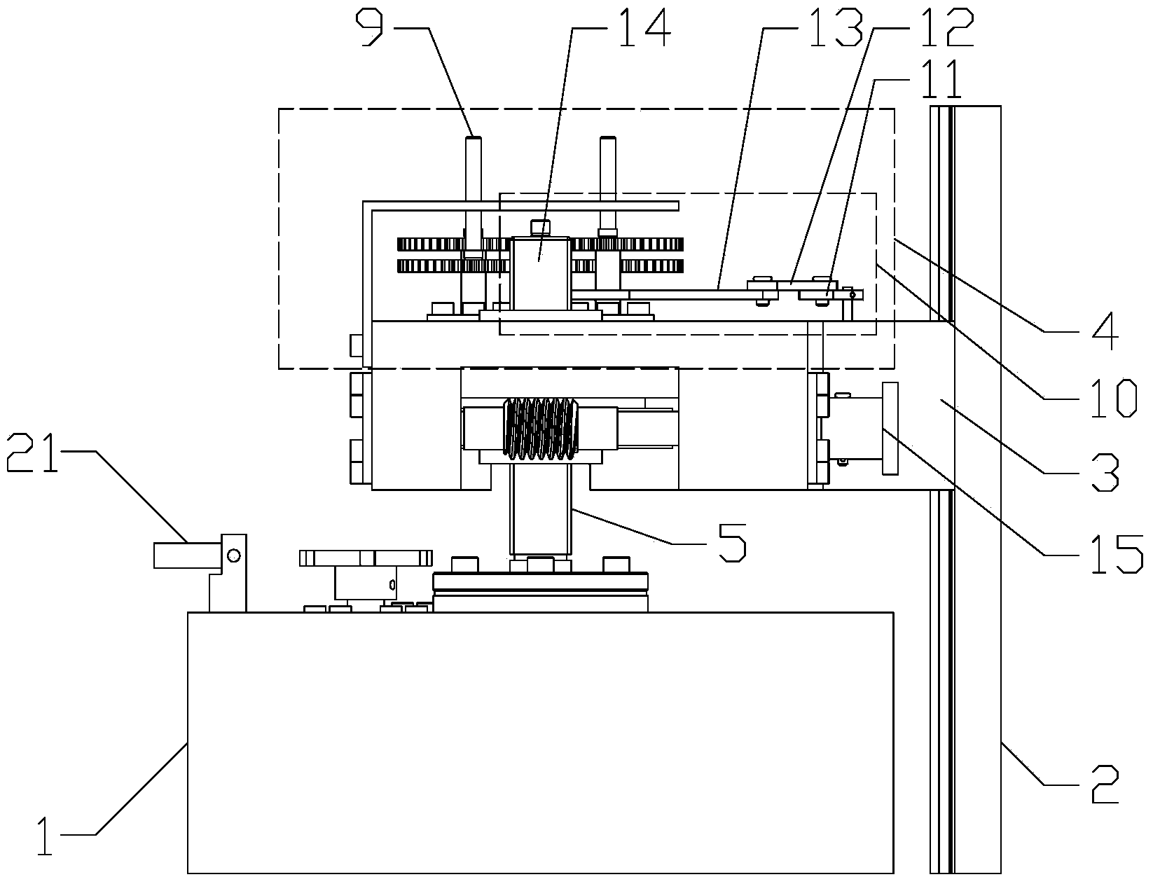
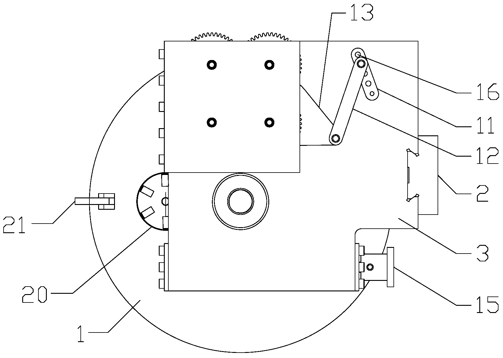
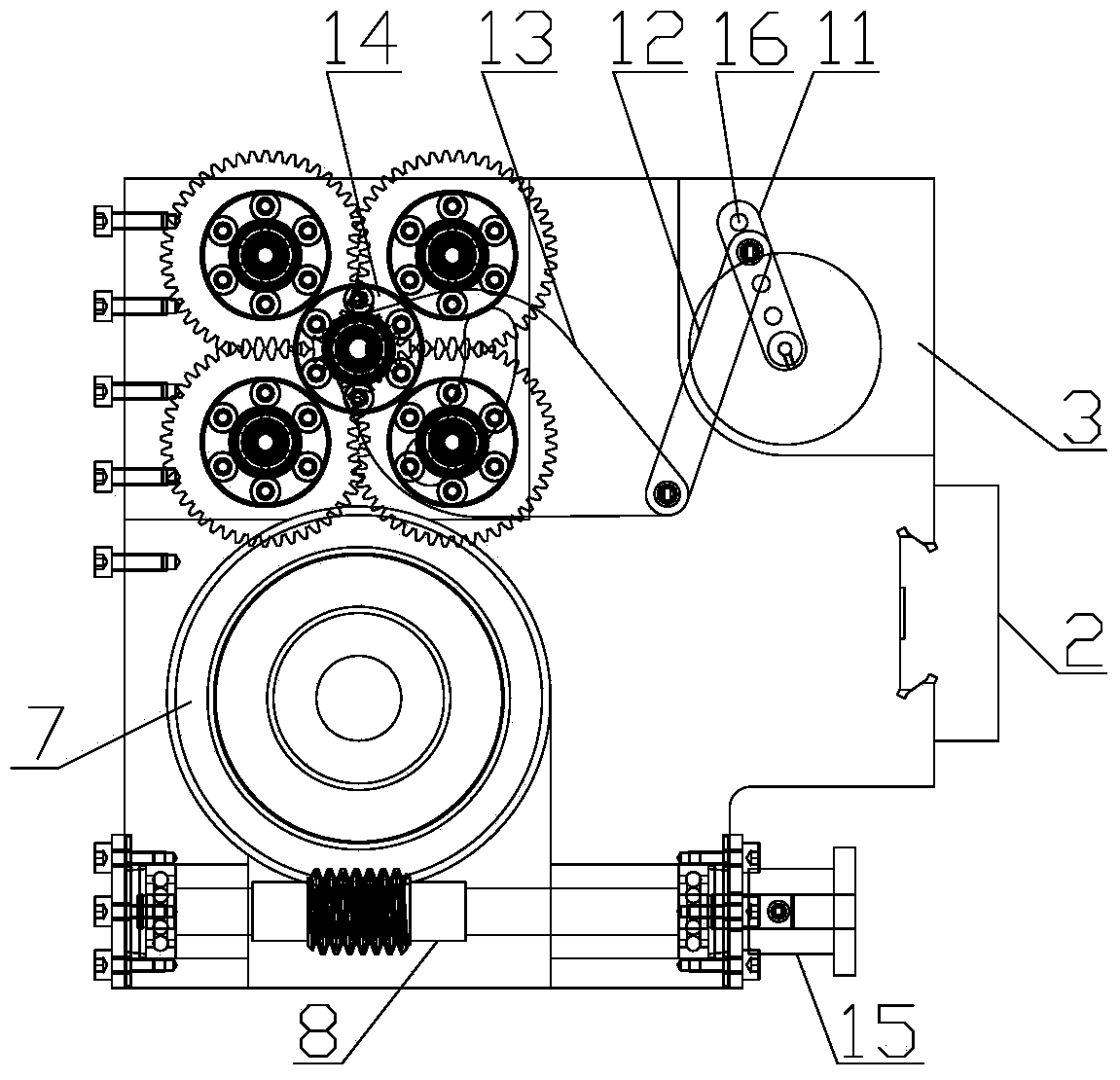
[0032] Such as figure 1 , figure 2 , image 3 and Figure 4 A biomechanical generator shown includes: a base 1, a dovetail guide rail 2 arranged on the upper end surface of the vertical base 1, a workbench main body 3 assembled with the dovetail guide slide rail 2 through a dovetail groove, and a workbench main body 3 arranged on the workbench The biomechanical mechanism of the end face 4;

[0033] The upper end surface of the base 1 is vertically provided with a threaded rod 5, and the lower end of the threaded rod 5 extends into the inside of the base 1; the inside of the base 1 is provided with a gear mechanism 6 for driving the rotation of the threaded rod 5, and the gear mechanism 6 includes at least two stages of gears;

[0034] The lower end surface of the workbench main body 3 is provided with a turbine 7, and the turbine 7 and the workbench main body 3 are rotationally assembled, that is, the turbine 7 can freely rotate relative to the workbench main body 3; The ...


PUM


Abstract

The invention discloses a biochemical generator, which comprises a base, a dovetail guide sliding rail, a workbench main body and a biomechanical generation mechanism, wherein the dovetail guide sliding rail is perpendicular to the upper end face of the base; the workbench main body is matched with the dovetail guide sliding rail through a dovetail groove; the biomechanical generation mechanism is arranged on the upper end face of a workbench; a threaded rod is perpendicularly arranged on the upper end face of the base; a gear mechanism for driving the threaded rod to rotate is arranged in the base; a worm gear is arranged on the lower end face of the workbench main body, and is assembled with the workbench main body in a rotating way; a worm for driving the worm gear to rotate is arranged on the workbench main body; the worm gear is sleeved on the threaded rod, and is in threaded fit with the threaded rod. According to the biochemical generator, the workbench is quickly lifted through a rough adjustment device (the gear mechanism), and is lifted by a minor distance through a fine adjustment device (a worm gear and worm matching mechanism), and a crank-link mechanism is driven by a motor to drive a simulated mechanical contact of the biochemical generation mechanism to reciprocally rotate, so that virtual shear force is generated on the surface of a biological membrane on the contact by the swinging of the biological membrane.

Description

technical field [0001] The invention relates to a biomechanical generator. Background technique [0002] With the continuous development of medicine, especially the development of orthopedics, the cross-fusion between it and biomechanics is getting closer and closer. In the field of orthopedics, the degeneration of the spine and its intervertebral disc is a common disease, but currently The direction of research is mainly focused on the model of spine and intervertebral disc degeneration caused by mechanical stimulation on living animals, and then the mechanism of degeneration is studied through cytology, molecular biology, immunology detection and analysis. Such research is at the stage of cytology It is a static research, which is to analyze the morphology and cytoskeleton of the cells in the end state of stress. At present, there is no device that can completely simulate the dynamic stress and compound stress state of the normal human spine and intervertebral disc, which ...

Claims


Application Information

Patent Timeline
Patent Type & Authority Applications(China)
IPC IPC(8): C12M1/00
CPCC12M35/04
Inventor 王卫明万朝燕陈秉智向先祥赵东洋
Owner 王卫明
Why Eureka
Try Eureka