Method for welding aluminum target assemblies

A welding method and technology of aluminum target, applied in welding equipment, welding equipment, welding/welding/cutting items, etc., can solve the problems of high cost, high pollution, high energy consumption, etc., to reduce energy consumption, reduce pollution, and save costs Effect

A welding method and technology of aluminum target, applied in welding equipment, welding equipment, welding/welding/cutting items, etc., can solve the problems of high cost, high pollution, high energy consumption, etc., to reduce energy consumption, reduce pollution, and save costs Effect

CN103567583AActive Publication Date: 2014-02-12KONFOONG MATERIALS INTERNATIONAL CO LTD

Image

  • Method for welding aluminum target assemblies

Examples


Embodiment Construction

[0033] In order to make the above objects, features and advantages of the present invention more comprehensible, specific implementations of the present invention will be described in detail below.

[0034] In the following description, specific details are set forth in order to provide a thorough understanding of the present invention. However, the present invention can be implemented in many other ways than those described here, and those skilled in the art can make similar extensions without departing from the connotation of the present invention. Accordingly, the present invention is not limited to the specific embodiments disclosed below.

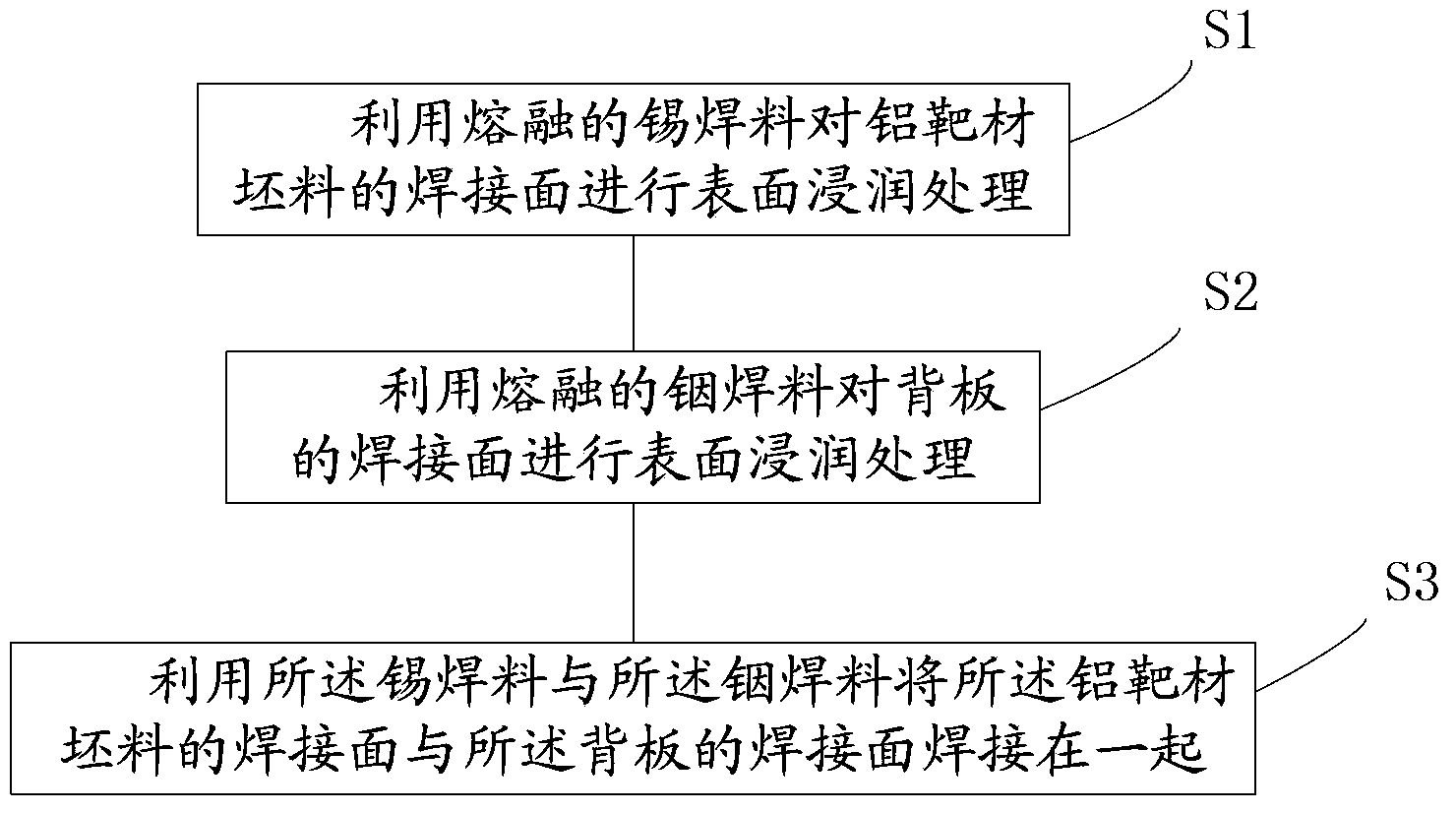
[0035] Please refer to figure 1 , figure 1 It is a schematic flow chart of the welding method of the aluminum target assembly provided by the present invention. The welding method of the aluminum target assembly provided by the present invention comprises the following basic steps:

[0036] Step S1: using molten tin solder to perfo...


PUM


Abstract

The invention provides a method for welding aluminum target assemblies. The method includes wetting welded surfaces of aluminum target blanks by molten tin solder; wetting welded surfaces of back plates by molten indium solder; welding the welded surfaces of the aluminum target blanks with the welded surfaces of the back plates by the tin solder and the indium solder. The method for welding the aluminum target assemblies has the advantages that nickel plating on the welded surfaces of the aluminum target blanks can be omitted, accordingly, energy consumption can be reduced, the cost can be saved, and pollution can be decreased.

Description

technical field [0001] The invention belongs to the field of semiconductor technology, and in particular relates to a welding technology of a target material and a back plate. Background technique [0002] In the semiconductor industry, the target assembly consists of a target that meets the sputtering performance and a back plate with a certain strength. The back plate can play a supporting role in assembling the target component to the sputtering base, and has the effect of conducting heat. [0003] Usually the target and the backing plate are welded to form a target assembly. Target components are usually larger in size, especially in LCD target components. The length and width of the 5th generation LCD target component exceeds 1.5m, while the length of the 8th generation LCD target component exceeds 2m. Due to the large size of the target assembly, the target assembly is prone to large deformation during high temperature welding. If traditional tin-based solder with h...

Claims


Application Information

Patent Timeline
12 Feb 2014
Publication
CN103567583A
IPC
B23K1/00; B23K1/20
CPC
B23K20/023; B23K20/24; B23K2103/18
Inventors
姚力军; 相原俊夫