Method for machining megawatt wind turbine blade mould

A wind power blade and megawatt-level technology, which is applied in the field of processing megawatt-level wind power blade molds, can solve the problems of high CNC machining cost, unfavorable project development, and long production and processing cycle, so as to improve production efficiency, shorten production cycle, and save space. use less effect

Active Publication Date: 2014-02-12
东方电气(天津)风电叶片工程有限公司
View PDF5 Cites 9 Cited by
  • Summary
  • Abstract
  • Description
  • Claims
  • Application Information

AI Technical Summary

Problems solved by technology

[0007] There are many problems and shortcomings in the above three manufacturing methods, which are not conducive to the cost reduction and efficiency increase of the wind power blade industry. The main problems and shortcomings are:
[0008] 1. The main disadvantages of method 1 are: CNC processing costs are relatively high, and there are many manufacturing processes
[0009] 2. The main disadvantages of method two are: the processing cycle is too long, the controllability is poor, and it is inconvenient to implement the production plan; the service life is short;
[0010] 3. The main disadvantages of method three are: the blades that need to be formed are not conducive to the development of new projects; the processing cycle is too long; the controllability is poor; the service life is short;
[0011] 4. The disadvantages of the above three methods are: too many production processes, low utilization rate of master mold, large floor area, long production and processing cycle, which is not conducive to the development of new products
[0012] It can be seen that the traditional manufacturing method of megawatt-level wind power blade molds can no longer meet the requirements of the current development of the wind power industry, restricting the development of the wind power blade industry, and is not conducive to cost reduction and efficiency increase

Method used


Image

  • Method for machining megawatt wind turbine blade mould

Examples


Embodiment Construction

[0046] Specific examples of the present invention are as follows.

[0047] Firstly, a laser tracker is introduced to accurately test the molding line during the entire mold making to ensure the processing quality.

[0048] Secondly, use 3D software to design the structure of the entire mold, including flanges, steel frames, layers, heating layers, surface layers, etc., and formulate the manufacturing process.

[0049] The main steps of the preparation method are:

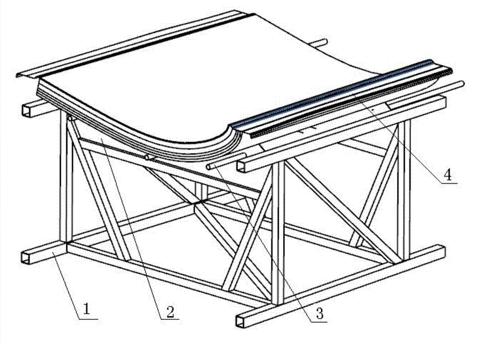
[0050] 1. Make a steel frame, install profiled steel plates every 2m on the steel frame, and distribute round steel in the middle of the profiled steel plates. Use laser tracker to detect and adjust the size and position of each place, such as figure 1 shown.

[0051] 2. Lay the smooth-surfaced skin laminates on the steel frame, connect them to the steel frame with self-tapping screws, and use the laser tracker to detect to ensure that the molded line of each place meets the design requirements.

[0052] 3. Lay a...


PUM


Abstract

The invention provides a method for machining a megawatt wind turbine blade mould. The method mainly comprises the following steps: 1, manufacturing a steel frame; 2, paving a thin-gauge skin laminated plate; 3, paving an isolation film; 4, manually pasting a pavement layer for the first time; 5, grinding and detaching part of the laminated plate, and connecting round steel and the steel frame firmly; 6, manually pasting a pavement layer for the second time; 7, paving a heating system layer; 8, manually pasting a pavement layer for the third time and curing; 9, machining the surface of the mould; 10, spraying a high-gloss gel coat and performing water mill; 11, checking and accepting. The method has the advantages that 1, a conventional mould manufacturing mode is changed, a mater mould machining link is skipped, and the production period is shortened; 2, the manufacturing cost is reduced, and the manufacturing efficiency is improved; 3, manufacturing processes are small in quantity and simple; 4, the controllability is high; 5, the requirement on master mould machining capacity is low; 6, the occupied space is small, and the occupied floor is small; 7, the cost reduction and the efficiency improvement of the mould are facilitated.

Description

technical field [0001] The invention relates to a method for processing a mold of a megawatt wind power blade, belonging to the technical field of wind power. Background technique [0002] There are basically three ways to make megawatt-level wind blade molds in the wind power industry: [0003] 1. Use CNC machining center (CNC) to process the master mold, and then remake the mold; [0004] 2. Use plywood and skin structure to make the master model, and then reproduce the mold; [0005] 3. Use the blade to turn the mold. [0006] The traditional manufacturing methods of megawatt-scale wind power blade molds are inseparable from the production of master molds, and the quality of master molds has a great influence on the quality and life of later molds. [0007] There are many problems and shortcomings in the above three manufacturing methods, which are not conducive to the cost reduction and efficiency increase of the wind power blade industry. The main problems and shortc...

Claims


Application Information

Patent Timeline
Patent Type & Authority Applications(China)
IPC IPC(8): B29C33/38B29C70/38
Inventor 吴海亮何涛许蕾
Owner 东方电气(天津)风电叶片工程有限公司
Why Eureka
Try Eureka