Freeze-thaw cycle testing machine

A freeze-thaw cycle and testing machine technology, applied to measuring devices, instruments, scientific instruments, etc., can solve the problems of increased laboratory noise emissions, high maintenance costs, waste of power, etc., to achieve strong adaptability to the working environment and reduce energy consumption , the effect of improving work efficiency

Inactive Publication Date: 2014-02-12
李健
View PDF4 Cites 6 Cited by
  • Summary
  • Abstract
  • Description
  • Claims
  • Application Information

AI Technical Summary

Problems solved by technology

At present, all kinds of freeze-thaw cycle testing machines used are heated by electric heating tubes, which are simple in structure and easy to use, but have low heat conversion efficiency. Generally, equipment equipped with 28 concrete specimens requires at least 10KW of power In order to meet the requirements of rapid temperature rise, and there is a danger of electric leakage in the heating of the electric heating tube, which increases the risk factor during the use of the testing machine
The refrigeration methods all use compressor refrigeration. The heat generated by the compressor during refrigeration is mainly discharged in two ways. One uses fan heat exchanger heat exchanger to discharge, and uses forced air flow to dissipate heat. In the process of fan-type heat exchanger heat exchanger, it is greatly affected by the ambient temperature. In summer, especially when the temperature is above 30°C, the cooling efficiency of the compressor is too reduced, and the manufacturer has to increase the temperature in the design. The power of the large fan heat exchanger and compressor not only wastes power, but also increases the noise emission of the laboratory, and due to the change of ambient temperature, the test has unstable factors, resulting in errors in the results.
The other is water-cooled heat dissipation, that is, cooling water towers are used to dissipate heat. Although cooling water towers are ideal for heat dissipation, the entire cooling system has complex structural design and high maintenance costs, and has been gradually eliminated by various manufacturers.

Method used


Image

  • Freeze-thaw cycle testing machine
  • Freeze-thaw cycle testing machine
  • Freeze-thaw cycle testing machine

Examples


Embodiment Construction

[0015] The present invention will be further described below in conjunction with accompanying drawing:

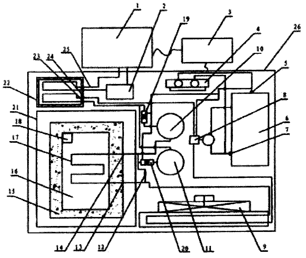
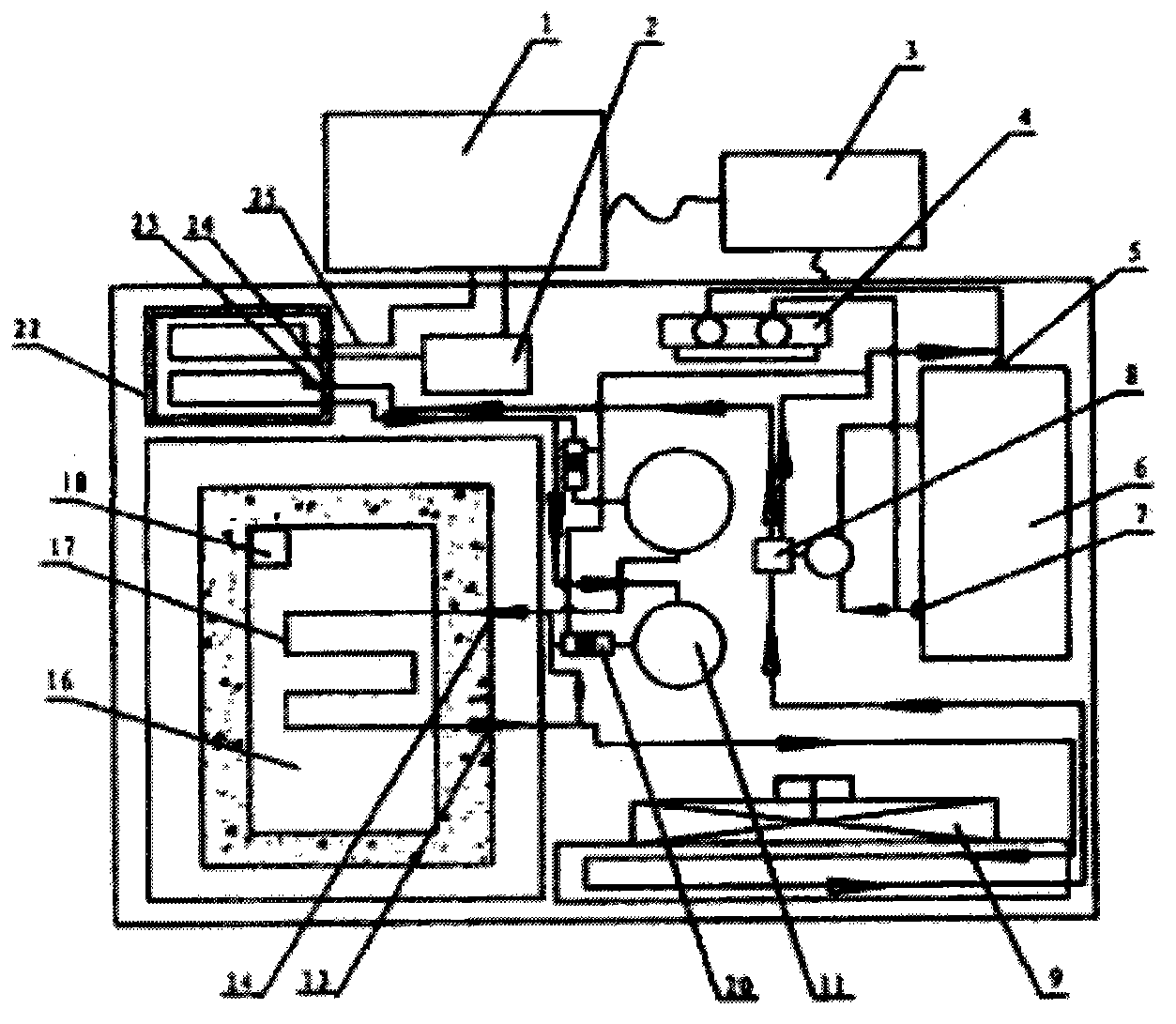
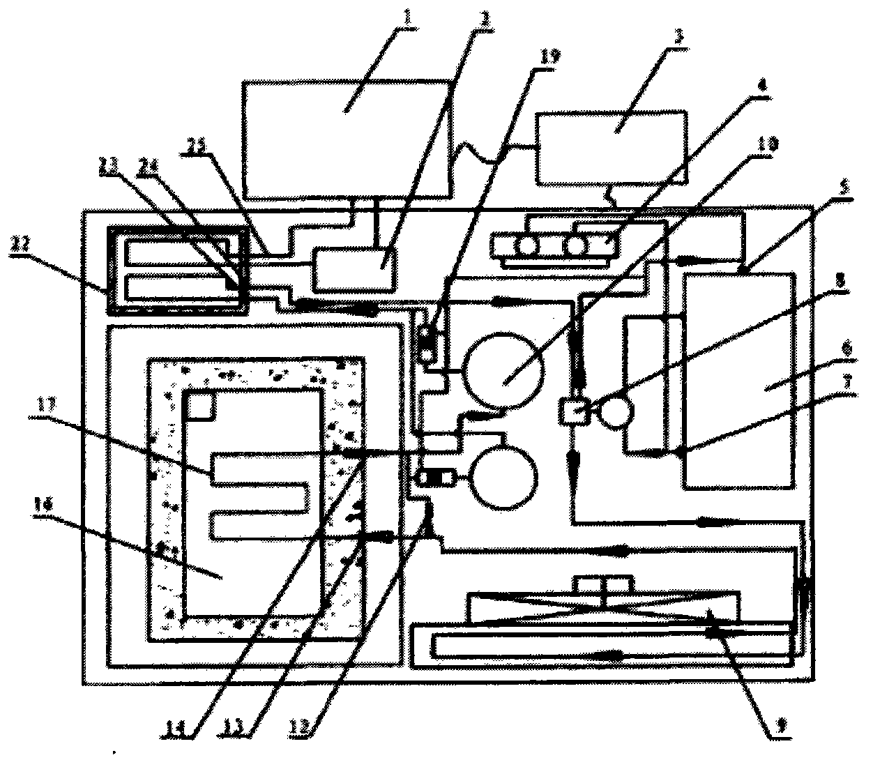
[0016] Such as figure 1 As shown, the freeze-thaw cycle testing machine of the present invention includes a cooling and heat exchange unit 26, a test piece box 1 and a control device 3.

[0017] The cooling and heat exchange unit 26 includes a refrigerant compressor 6, a plate heat exchanger 22, a fan heat exchanger 9, a pressure protection device 4 and an energy storage device. The refrigerant compressor 6, the plate heat exchanger 22, the fan heat exchanger 9 and the energy storage device are respectively fixed on the base of the cooling and heat exchange group 26 box body, and the two interfaces of the pressure protection device 4 are respectively connected to the refrigerant compressor. On the high-pressure port 7 and low-pressure port 5 of the machine, the blue controls the pressure at both ends of the refrigerant compressor 6, and converts the pressure signal into an...


PUM


Abstract

The invention provides a freeze-thaw cycle testing machine, comprising a cold and heat exchange set, a test piece box and a control device, wherein the control device is respectively connected with the cold and heat exchange set and the test piece box and controls the cold and heat exchange set and the test piece box to operate; and the cold and heat exchange set further comprises an energy storage device which is connected between a plate-type heat exchanger and a fan-type heat exchanger in the cold and heat exchange set. The energy storage device is used for storing one part of energy which needs to be given up in a previous refrigeration or heating process of the test piece box and releasing the stored energy in a next corresponding refrigeration or heating process, so that the speed of the refrigeration or heating process is improved, a large quantity of waste gas energy is recycled, the energy consumption is reduced, the working efficiency is improved, the speed of heating and refrigeration is guaranteed, and noises are small. The freeze-thaw cycle testing machine is well-adapted to working environments and is applicable to various test sites and natural environments.

Description

technical field [0001] The invention relates to a test device, in particular to a freeze-thaw cycle test machine with fast freezing and melting. Background technique [0002] The freeze-thaw cycle test machine is a test machine for quickly simulating environmental changes when testing material stability and durability. It is often used in the fields of construction and material science to test the safety performance and durability of various materials used under the condition of artificially simulating the temperature rise and fall of the environment. Generally do a test, the equipment needs to run continuously for about 30 days for a long time. At present, all kinds of freeze-thaw cycle testing machines used are heated by electric heating tubes, which are simple in structure and easy to use, but have low heat conversion efficiency. Generally, equipment equipped with 28 concrete specimens requires at least 10KW of power In order to meet the requirements of rapid temperatur...

Claims


Application Information

Patent Timeline
Patent Type & Authority Applications(China)
IPC IPC(8): G01N25/00
Inventor 李健
Owner 李健
Why Eureka
Try Eureka