Time controlling device for fast heating soldering iron

A technology of time control and overtime control, applied in the direction of program control, computer control, general control system, etc., can solve problems such as hidden safety hazards and poor effects, and achieve the effect of ensuring output time, wide voltage adaptability, and avoiding fire hazards.

Active Publication Date: 2014-02-12
JULONG
View PDF6 Cites 1 Cited by
  • Summary
  • Abstract
  • Description
  • Claims
  • Application Information

AI Technical Summary

Problems solved by technology

[0004] Aiming at the disadvantages of the binding machine in the prior art that have poor control effect on the sticking and cutting of the binding tape, and the potential safety hazards generated during use, the technical problem to be solved by the present invention is to provide a binding machine that does not change with the voltage and can ensure binding. Fast heating soldering iron time control device with sticky cutting quality and safety and reliability

Method used


Image

  • Time controlling device for fast heating soldering iron
  • Time controlling device for fast heating soldering iron
  • Time controlling device for fast heating soldering iron

Examples


Embodiment Construction

[0023] The present invention will be further described in detail below in conjunction with the accompanying drawings and embodiments.

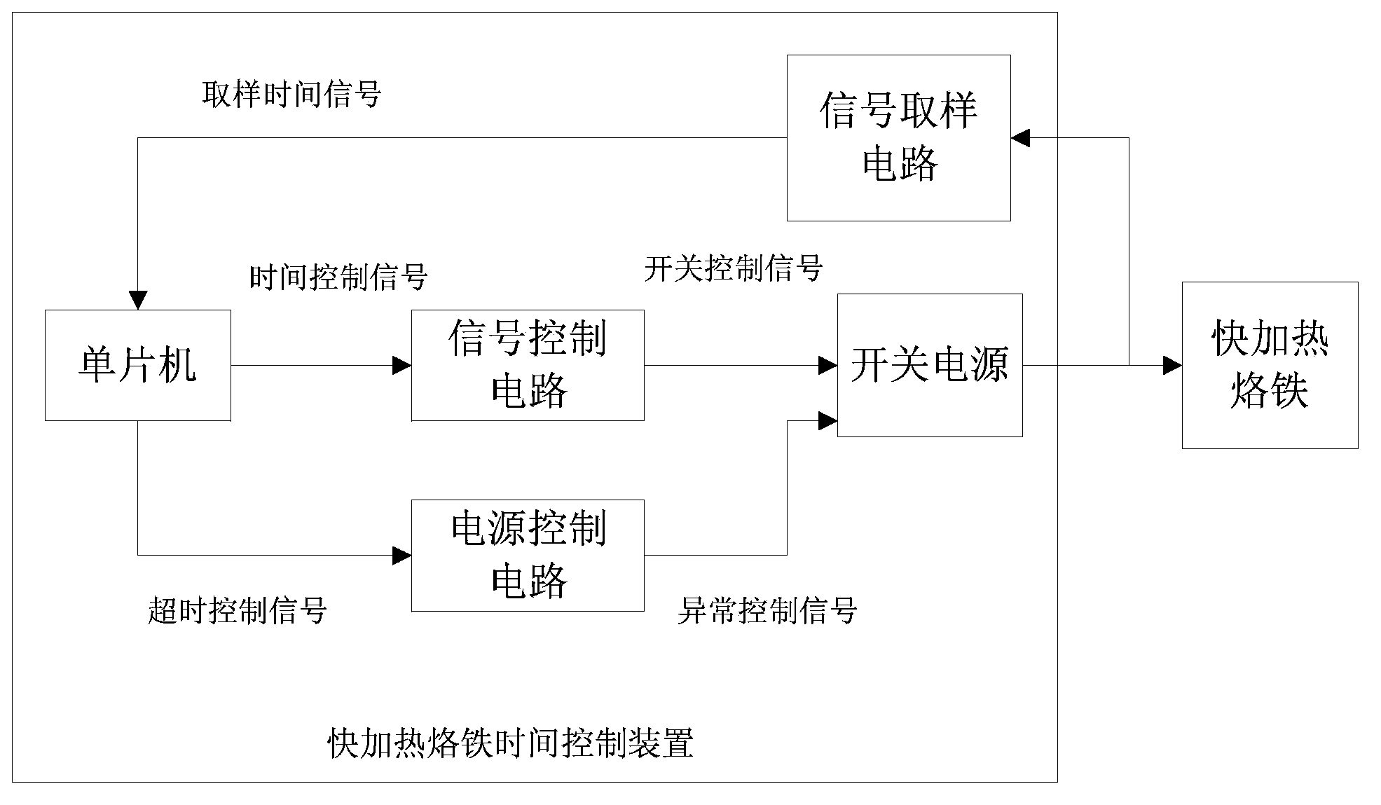
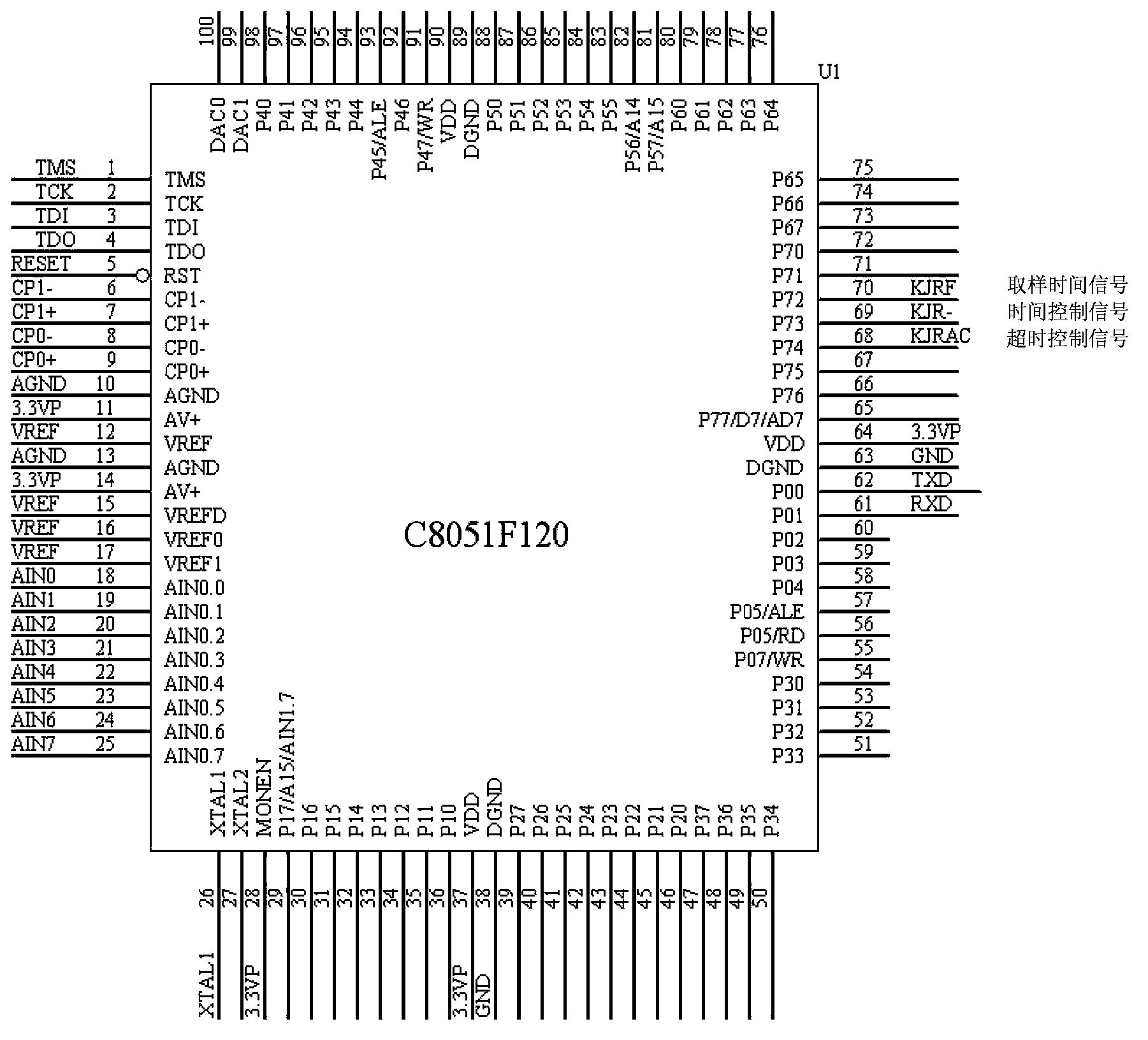
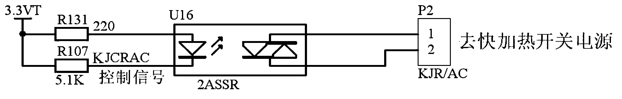
[0024] The fast heating soldering iron time control device of the present invention is based on the single-chip microcomputer U1 (this example adopts C8051F120) in the control circuit, controls the fast heating time through the signal control circuit, the signal sampling circuit takes samples, compares the input and output working time, and maintains the constant temperature of the soldering iron. In abnormal circumstances, the fast heating power supply is shut off through the power supply control circuit. The signal control circuit realizes the protection of the abnormal situation of the single chip microcomputer.

[0025] Such as Figure 1-5 As shown, the present invention takes the single-chip microcomputer U1 as the core, and according to the working sequence requirements of the fast-heating soldering iron of the tie-down machine, first e...


PUM


Abstract

The invention relates to a time controlling device for fast heating soldering iron. The time controlling device comprises a single-chip microcomputer, a power supply control circuit, a signal control circuit and a signal sampling circuit, wherein the single-chip microcomputer is used for carrying out closed-loop control over the sampling time and time-out control over the feedback time on the fast heating soldering iron. The power supply control circuit is used for controlling the on-off state of a switching power supply, the signal control circuit is used for preventing the single-chip microcomputer from outputting an abnormal signal, and the signal sampling circuit is used for sampling the voltage of a working signal sent by the switching power supply to the fast heating soldering iron and converting the working signal into a sampling time signal to be fed back to the single-chip microcomputer. By means of the time controlling device, the stable work of the fast heating soldering iron can be effectively guaranteed, closed-loop control is adopted, error compensation control is precise, working efficiency is high, the waste of strapping belts is reduced, and meanwhile dangers caused by the abnormity of the single-chip microcomputer or the loss of control of a fast heating load in the process of working are avoided.

Description

technical field [0001] The invention relates to a fast-heating soldering iron in a tie-bar machine, in particular to a fast-heating soldering iron time control device used in financial equipment. Background technique [0002] The bank system of our country mainly adopts the automatic binding machine to bind and bundle 100 banknotes. At present, the binding machine generally uses a fast heating iron without preheating. The quality of sticking and cutting affects the binding effect of banknotes. The transformer controls the fast heating soldering iron, and its temperature will change with the change of the mains power supply voltage. In the past, the heating gear was adjusted manually according to the sticking effect. First, the operation is troublesome, because the mains power supply voltage fluctuates, and some The regional voltage fluctuates greatly, which requires the operator to adjust the heating gear frequently according to the sticking and cutting effect; secondly, it ...

Claims


Application Information

Patent Timeline
Patent Type & Authority Applications(China)
IPC IPC(8): G05B19/042
Inventor 柳长庆柳永诠柳伟生殷忠吴文良于淼张玉峰
Owner JULONG
Why Eureka
Try Eureka