Frequency converter with rotating speed tracking function and rotating speed tracking method with the frequency converter

A frequency converter and speed technology, applied in the field of frequency converter, can solve problems such as large frequency converter recovery, sudden drop in bus voltage of the frequency conversion system, endangering the stability of power electronic equipment, etc., and achieve the effect of shortening the response time

Active Publication Date: 2014-02-12
SHENZHEN EASYDRIVE ELECTRIC
View PDF4 Cites 10 Cited by
  • Summary
  • Abstract
  • Description
  • Claims
  • Application Information

AI Technical Summary

Problems solved by technology

[0002]Many loads in the industrial field are composed of induction motors. The problem will cause the working state of the motor to switch between start and stop frequently, and due to the existence of power loss residual voltage, it may cause large inrush current and inrush torque when the inverter resumes starting
The surge current may cause the bus voltage of the frequency conversion system to drop suddenly, which may cause the action of the power line protection device and cause the motor to fail to start
The impact torque m

Method used


Image

  • Frequency converter with rotating speed tracking function and rotating speed tracking method with the frequency converter
  • Frequency converter with rotating speed tracking function and rotating speed tracking method with the frequency converter
  • Frequency converter with rotating speed tracking function and rotating speed tracking method with the frequency converter

Examples


Embodiment Construction

[0028] In order to make the object, technical solution and advantages of the present invention more clear, the present invention will be further described in detail below in conjunction with the accompanying drawings and embodiments. It should be understood that the specific embodiments described here are only used to explain the present invention, not to limit the present invention.

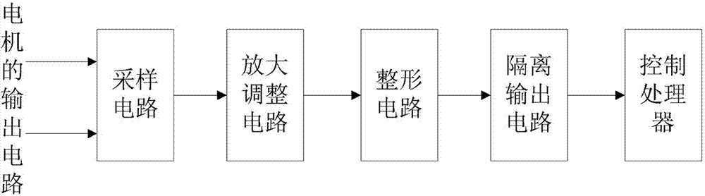
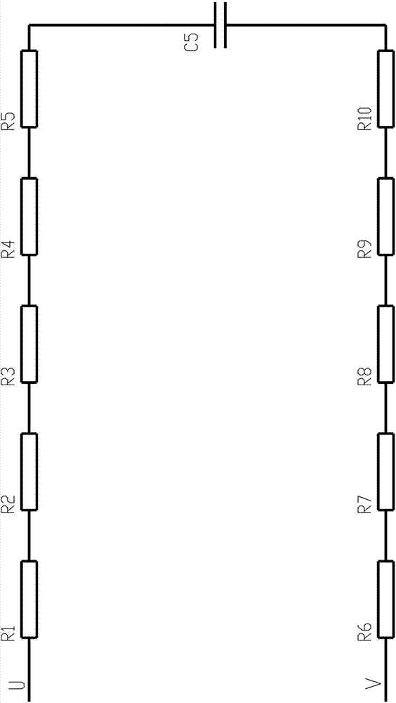
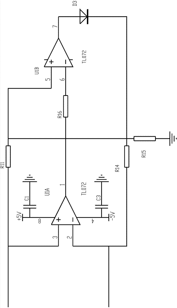
[0029] see Figure 1 to Figure 4 , the present invention is a frequency converter with speed tracking function, which is connected to the output circuit of the motor, including: a sampling circuit connected to any two phases of the output circuit U / V / W of the motor, and sequentially according to the circuit flow sequence Connected amplification adjustment circuit, shaping circuit, isolated output circuit;

[0030] The sampling circuit is used to step down the motor residual voltage signal received from the output circuit of the motor and then input it to the amplification adjustment circuit; si...


PUM


Abstract

The invention relates to the technical field of frequency converters, in particular to a frequency converter with the rotating speed tracking function and a rotating speed tracking method with the frequency converter. The frequency converter comprises a sampling circuit, an amplification adjusting circuit, a shaping circuit and an isolation output circuit, wherein the sampling circuit is connected with any two phases in an output circuit of a motor, and the amplification adjusting circuit, the shaping circuit and the isolation output circuit are sequentially connected according to the circuit flow direction sequence. In the amplification adjusting circuit, after difference amplification and waveshape conversion are carried out on residual voltage signals, shaping is carried out through the shaping circuit, and the frequency of pulse signals is calculated by controlling a processor. The residual voltage frequency of the motor is detected and processed through a hardware circuit to obtain the more accurate voltage value, then the voltage value is utilized for achieving rotating speed tracking of the motor, and the rotating speed of the motor is obtained. Due to the fact that the residual voltage signals of the motor can be directly obtained from the motor, repeated attempts are not required, the reaction time is greatly shortened, the impact caused by a current to equipment is also reduced, efficiency is greatly improved, misinformed current faults of the equipment are reduced, and the service life of the equipment is prolonged.

Description

technical field [0001] The invention relates to the technical field of frequency converters, in particular to a frequency converter with a speed tracking function and a speed tracking method using the same. Background technique [0002] Many loads in the industrial field are composed of induction motors. In actual work, due to motor work requirements, industrial site process requirements, and short-term power failures, etc., the working state of the motor will be frequently between start and stop. Switching, and due to the existence of power-off residual voltage, large inrush current and inrush torque may be caused when the inverter resumes to start. The inrush current may cause a sudden drop in the bus voltage of the frequency conversion system, which may cause the action of the power line protection device and cause the motor to fail to start. The impact torque may cause damage to the motor stator coil, load, etc. At the same time, the rich harmonic components will also l...

Claims


Application Information

Patent Timeline
IPC IPC(8): H02M1/00H02P27/04G01P3/481
CPCY02P80/10
Inventor 许景翔
Owner SHENZHEN EASYDRIVE ELECTRIC
Why Eureka
Try Eureka