Biological impedance imaging device

A bioelectrical impedance, imaging device technology, applied in medical science, sensors, diagnostic recording/measurement, etc., can solve the problems of weak and difficult imaginary part demodulation output signal, save control IO port, simple circuit optimization, impedance The effect of accurate information

Inactive Publication Date: 2014-02-19
NANJING UNIV OF POSTS & TELECOMM
View PDF4 Cites 16 Cited by
  • Summary
  • Abstract
  • Description
  • Claims
  • Application Information

AI Technical Summary

Problems solved by technology

When the imaginary part of the impedance is small, the demodulated output signal of the imaginary part is relatively weak. At this time, it is difficult to achieve a certain accuracy by using hardware analog demodulation.

Method used


Image

  • Biological impedance imaging device
  • Biological impedance imaging device
  • Biological impedance imaging device

Examples


Embodiment Construction

[0024] The present invention will be further described in detail below in conjunction with the accompanying drawings and specific implementation methods.

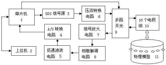
[0025] The present invention designs a kind of bioelectrical impedance hardware system based on single-chip microcomputer technology, and this system is as figure 1 shown.

[0026] The DDS signal source 3 can use the DDS integrated chip of Analog Devices, and use its internal 8-bit parallel port or serial port to continuously read the sinusoidal signal sampling data from the EPROM of the microcontroller 1, and generate EIT after D / A conversion and filtering desired sinusoidal signal. The DDS signal source 3 includes a programmable DDS system, a high-performance DAC and a high-speed comparator, a frequency synthesizer and a clock generator that can realize full digital programming. Connected to a precision clock source, a spectrally clean analog sine wave output with programmable frequency and phase can be generated. This...


PUM


Abstract

The invention discloses a biological impedance imaging device. The biological impedance imaging device comprises a single-chip microcomputer (1), an upper computer (2), a DDS signal source (3), an A / D conversion circuit (4), a low-pass filtering circuit (5), a voltage-current conversion circuit (6), a signal amplifying circuit (7), a phase-sensitive demodulation circuit (8), multi-way switches (9), a plurality of electrode sets (10) and a physical model (11). The biological impedance imaging device has the advantages that a generated current source has high output resistance, and therefore the independence between output current and load voltage can be guaranteed; each set of switches needs eight-digit IO ports for controlling, the control end of an analog switch is connected with a latch circuit, in this way, two sets of switches can be controlled through an 8+2 digital address line, the number of the IO ports for controlling the single-chip microcomputer is reduced, and then the circuit is simpler and optimized; besides, real part information and imaginary part information of impedance can be obtained through the phase-sensitive demodulation circuit, so that the impedance information obtained through the biological impedance imaging device is more accurate compared with a method for taking the real part information of the impedance only.

Description

technical field [0001] The invention relates to a medical device, in particular to a hardware system for measuring bioelectrical impedance. Background technique [0002] Electrical Impedance Tomography (EIT) is based on the physical principle that the electrical impedance characteristics of different tissues in the human body are different. By injecting a small safe AC current into the human body, an electric field distribution is formed inside the human body. A regular potential will be formed, and the image of the internal resistivity distribution of the human body will be reconstructed by measuring the surface potential of the human body. Due to the broad application prospects of EIT technology, it has attracted a large number of experts and scholars to invest in the research ranks. According to incomplete statistics, there are currently more than 30 research groups in the United States, Britain, Russia, Germany, France, Sweden, Japan, and India conducting research on EI...

Claims


Application Information

Patent Timeline
Patent Type & Authority Applications(China)
IPC IPC(8): A61B5/053
Inventor 戎舟马晓妮刘瑞兰唐超
Owner NANJING UNIV OF POSTS & TELECOMM
Why Eureka
Try Eureka