Distributed Time Difference Receiver System Based on Photoelectric Technology

A photoelectric technology, distributed technology, applied in the direction of wavelength division multiplexing system, electromagnetic wave transmission system, radio wave measurement system, etc., can solve the problems of unfavorable substation layout flexibility, transmission loss change, and large signal impact, etc., to achieve Low cost, small signal loss, and strong electromagnetic compatibility

Active Publication Date: 2015-12-09
CHINA ELECTRONIC TECH GRP CORP NO 38 RES INST
View PDF8 Cites 0 Cited by
  • Summary
  • Abstract
  • Description
  • Claims
  • Application Information

AI Technical Summary

Problems solved by technology

Especially when the distance between each receiving sub-station is relatively long (usually tens of meters to several kilometers), the loss caused by the microwave cable is more than ten dB to several hundred dB; secondly, even if the transmission loss is compensated by the amplifier, the receiving Once the location of substations changes, the transmission loss will also change greatly. The above two points are not conducive to the flexibility of substation layout
In addition, in this way, due to the limitation of the microwave cable's own structural principle, the signal transmitted through the microwave cable is greatly affected by the external electromagnetic environment
Moreover, microwave cables need to lay a large number of pipelines, and when converging from each receiving substation to the control center, the diameter of the microwave cables is thicker, and additional shielding processes and equipment are required to avoid interference between microwave cables, which directly leads to increased costs and laying Difficulties, high cost of later maintenance, difficult maintenance and other issues

Method used


Image

  • Distributed Time Difference Receiver System Based on Photoelectric Technology

Examples


Embodiment Construction

[0020] The structural features of the present invention will now be described in detail in conjunction with the accompanying drawings.

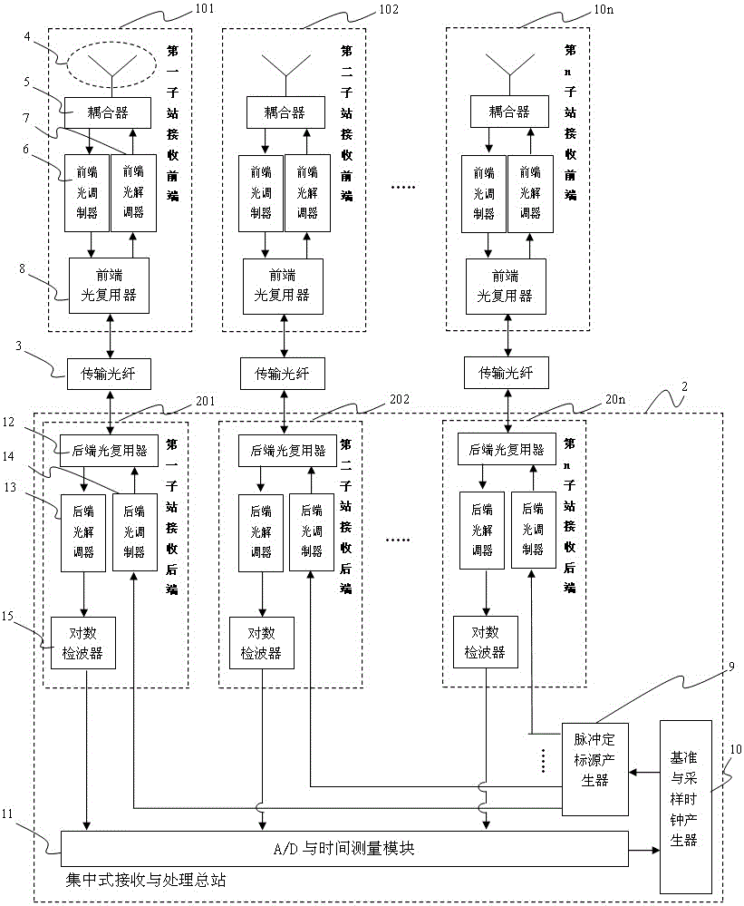
[0021] see figure 1 , a distributed time-difference receiver system based on photoelectric technology, including n sub-station receiving front-ends and a centralized receiving and processing station 2. The value range of n is between 8 and 20; the n sub-station receiving front-ends They are sequentially numbered as the receiving front end 101 of the first substation, the receiving front end 102 of the second substation, ... until the receiving front end 10n of the nth substation.

[0022] Each substation receiving front-end is composed of antenna 4, coupler 5, front-end optical modulator 6, front-end optical demodulator 7 and front-end optical multiplexer 8, wherein the coupler 5 has two signal input ports and one signal output port , the signal communication end of the antenna 4 is connected to one of the signal input ports of the coupler 5...


PUM


Abstract

The invention provides a distributed type time difference receiving machine system based on the photoelectric technology for overcoming the defects of a cable type multi-point positioning system. The distributed type time difference receiving machine system comprises 8 to 20 substation receiving front ends and a centralized type receiving and processing main station, wherein the substation receiving front ends are connected with the centralized type receiving and processing main station. In addition, each substation receiving front end is composed of an antenna, a coupler, a front end optical modulator, a front end optical demodulator and a front end optical multiplexer. The centralized type receiving and processing main station is composed of substation receiving rear ends, a pulse calibration source generator, a standard and sampling clock generator and an A / D and time measurement module, wherein the substation receiving front ends are connected with the centralized type receiving and the processing main station 2 through transmission optical fibers. The distributed type time difference receiving machine system has the main advantages that microwave signal transmission and calibration of a multi-station receiving machine are achieved through microwave photoelectric multiplexing, the stations are flexibly distributed, the time difference measurement accuracy is high, the electromagnetic compatibility is high, and the cost is relatively low.

Description

technical field [0001] The invention belongs to the technical field of azimuth monitoring and guidance of flying objects, in particular to a multi-station time-difference receiver based on photoelectric technology, and is especially suitable for a distributed time-difference receiver system of an airport level III integrated traffic and guidance radar system. The invention adopts microwave photoelectric multiplexing to realize microwave signal transmission and calibration of multi-station receivers, solves the problems of flexible station arrangement of distributed receivers, high precision of time difference measurement, strong electromagnetic compatibility, relatively low cost, etc., and has strong social effects and market value. Background technique [0002] At present, the monitoring and guidance of aircraft orientation by the civil aviation system is mainly realized through the airport level III integrated traffic monitoring and guidance system (also known as MLAT mult...

Claims


Application Information

Patent Timeline
Patent Type & Authority Patents(China)
IPC IPC(8): G01S5/06H04B10/25H04J14/02
CPCG01S5/10G01S7/003G01S7/285G01S7/42G01S13/003G01S13/913H04B10/25754
Inventor 张焱方立军柳勇马骏洪蕾郭雪锋
Owner CHINA ELECTRONIC TECH GRP CORP NO 38 RES INST
Why Eureka
Try Eureka