Metal source-drain structure and forming method thereof

A metal source and metal technology, applied in electrical components, circuits, semiconductor devices, etc., can solve problems such as large parasitic effects, high off-state current, high thermal overhead, etc., and achieve high electronic barrier height, simple structure, and simple process Effect

Active Publication Date: 2014-02-19
TSINGHUA UNIV
View PDF5 Cites 9 Cited by
  • Summary
  • Abstract
  • Description
  • Claims
  • Application Information

AI Technical Summary

Problems solved by technology

However, these processing methods usually have high thermal overhead, and are often accompanied by strong acid treatment when removing the sacrificial metal layer. For Ge-based devices, the gate stack structure composed of high-k dielectric and metal gate Generally cannot withstand such high temperature or strong acid treatment, these treatments may lead to deterioration of the electrical performance of the gate stack structure of MOSFET devices
In addition, the carrier Schottky barrier height of the currently obtained Ge-based Schottky junction is not particularly ideal, and the switching current ratio of the Schottky junction is not very high, so it will cause higher The off-state current and large parasitic effects will affect the switching current ratio of Ge MOSFET devices

Method used


Image

  • Metal source-drain structure and forming method thereof
  • Metal source-drain structure and forming method thereof
  • Metal source-drain structure and forming method thereof

Examples


Embodiment Construction

[0032] Embodiments of the present invention are described in detail below, examples of which are shown in the drawings, wherein the same or similar reference numerals designate the same or similar elements or elements having the same or similar functions throughout. The embodiments described below by referring to the figures are exemplary and are intended to explain the present invention and should not be construed as limiting the present invention.

[0033] In the present invention, unless otherwise clearly specified and limited, a first feature being "on" or "under" a second feature may include direct contact between the first and second features, and may also include the first and second features Not in direct contact but through another characteristic contact between them. Moreover, "above", "above" and "above" the first feature on the second feature include that the first feature is directly above and obliquely above the second feature, or simply means that the first feat...


PUM

PropertyMeasurementUnit
thicknessaaaaaaaaaa
thicknessaaaaaaaaaa
thicknessaaaaaaaaaa

Abstract

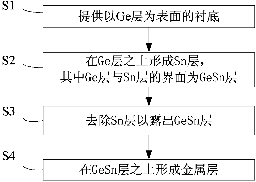
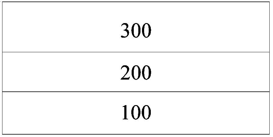
The invention provides a metal source-drain structure and a forming method thereof. The method includes the following steps of providing a substrate with a Ge layer as the surface, forming an Sn layer on the Ge layer, removing the Sn layer so as to expose a GeSn layer which is the interface between the Ge layer and the Sn layer and forming a metal layer on the GeSn layer. The metal source-drain structure and the forming method thereof can improve the on-off ratio of a component and the electronic barrier height of a Schottky component and have the advantages of being simple, easy to achieve and low in cost.

Description

technical field [0001] The invention relates to the field of semiconductor manufacturing, in particular to a metal source-drain structure and a forming method thereof. Background technique [0002] The semiconducting Ge has high electron and hole mobility and has great potential as a device channel material for novel high-performance metal-oxide-semiconductor field-effect transistors (MOSFETs). For small-sized MOSFET devices, suppressing the short-channel effect of the device is a very important issue. It is generally required that the source-drain pn junction depth of the device should be scaled down with the device size to weaken the two-dimensional potential distribution in the channel. Effect, enhance the control ability of the gate to the channel potential to suppress the short channel effect. Therefore, for extremely small-sized MOSFET devices, the ultra-shallow source-drain pn junction is the key to achieving good device performance. At the same time, the influence ...

Claims


Application Information

Patent Timeline
Patent Type & Authority Applications(China)
IPC IPC(8): H01L29/78H01L29/06H01L21/336H01L21/28
CPCH01L29/0847H01L29/47H01L29/66477H01L29/7839
Inventor 赵梅刘磊王敬梁仁荣许军
Owner TSINGHUA UNIV
Why Eureka
Try Eureka