Improved direct laser drilling processing method

A laser direct and processing method technology, applied in the direction of electrical components, printed circuit manufacturing, printed circuit, etc., can solve the problems of inconsistent ablation state of positioning targets, unstable production process, uneven residual thickness, etc., to ensure laser ablation Quality, elimination of inconsistencies in ablation state, and stable production process

Inactive Publication Date: 2014-02-19
DALIAN PACIFIC ELECTRONICS
View PDF6 Cites 13 Cited by
  • Summary
  • Abstract
  • Description
  • Claims
  • Application Information

AI Technical Summary

Problems solved by technology

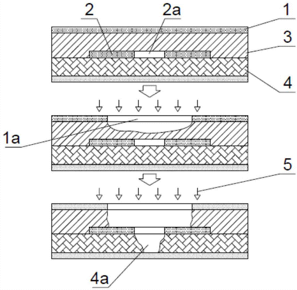
[0003] The positioning target of the traditional laser direct drilling technology generally adopts blackening or browning to pretreat the surface of copper foil, and then processes it by laser ablation; figure 2 As shown, it is a schematic diagram of the traditional laser direct drilling and burning target method. In the figure, the skylight layer copper foil 1 is pressed together by the prepreg 3 and the core material 4. Under the action of the laser beam 5, the skylight layer copper foil 1 is ablated At this time, the prepreg 3 has been partially ablated, and the remaining thickness is uneven; under the continuous action of the laser beam 5, the prepreg 3 at the lower part of the copper etching target area 1a is completely ablated, and through The alignment target hole 2a of the sub-outer receiving plate 2 is ablated towards the inside of the core material 4, forming holes of different depths, which may cause ablation and breakdown of the core material 4a in severe cases
It can be seen that due to the uneven pretreatment, the ablation state of the positioning target is inconsistent, the production process is unstable, and the production efficiency is seriously affected.

Method used


Image

  • Improved direct laser drilling processing method
  • Improved direct laser drilling processing method
  • Improved direct laser drilling processing method

Examples


Embodiment Construction

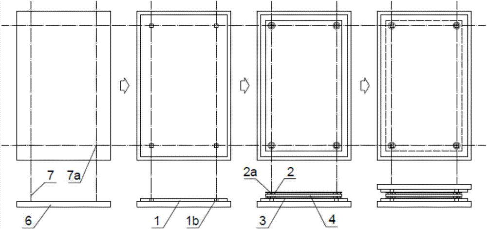
[0026] The invention provides an improved laser direct drilling method, such as figure 1 Shown is a schematic diagram of the lamination method of the present invention. When laminating the laminated boards, first spread a piece of skylight layer copper foil 1 on the lower mirror plate 6, and make its back glue face up; then use the infrared generator of the laminated board table to generate infrared rays to form four crossing light spots 7a, and Move the position of the light spot 7a so that it is aligned with the four window target areas 1b; take the printed board core material 4 that has been spot-welded and place it flat on the skylight layer copper foil 1 in the correct direction, and make the secondary outer edges of the four corners The layer receiving plate 2 is aligned with the four infrared intersection light spots 7a; finally, a skylight layer copper foil 1 is spread on the core material 4, with the adhesive side facing down, and the window opening target areas 1b a...


PUM


Abstract

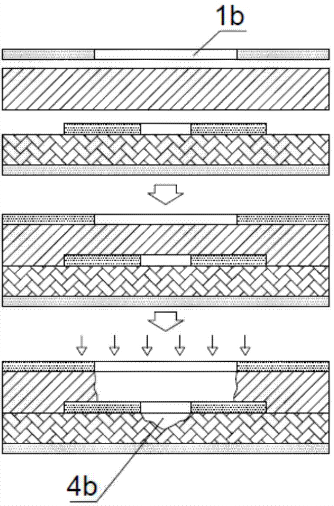
The invention discloses an improved direct laser drilling processing method. The improved direct laser drilling processing method is characterized by including the steps of laminating and direct laser drilling. The laminating includes the steps of opening a window in a copper foil on a skylight layer in a milled mode to form a window opening target region, conducting laminating processing by using a folded plate table infrared ray generator to generate infrared rays to form four intersected ray pots to locate window opening target regions when folded plates are laminated, and conducting melanism processing. The direct laser drilling includes the steps of conducting ablation on prepregs exposed out of the four window opening target regions of the copper foil on the skylight layer through a preset procedure, enabling a sub-outer-layer receiving disc and an aligning target hole to be exposed out, and conducting direct laser drilling with the aligning target hole serving as a location standard. According to the improved direct laser drilling processing method, the mode that the window is directly opened at the position of a location target in the copper foil on the skylight layer is adopted, the problem that the ablation state of the location target is inconsistent due to uneven preprocessing is thoroughly solved, the production process is stable, the production efficiency is obviously improved, the infrared ray intersected ray pots are used for locating, the location accuracy is improved, and the laser ablation quality of the aligning target hole is sufficiently guaranteed.

Description

technical field [0001] The invention relates to a laser drilling method, in particular to an improved laser direct drilling method. Background technique [0002] HDI is the abbreviation of High Density Interconnection (High Density Interconnection), a technology for producing printed boards, a circuit board with a relatively high circuit distribution density using micro-blind buried hole technology. While the electronic design is constantly improving the performance of the whole machine, it is also trying to reduce its space size, and at the same time build a denser logic network in a limited space. In small portable products from mobile phones to smart weapons, the device pitch is smaller and the I / O More packages with O-pins and embedded passives have increasingly shorter response times and higher frequencies, all of which require smaller PCB feature sizes, which is driving a strong demand for HDI / miniature vias. A hole with a diameter of less than 150um is called a micro...

Claims


Application Information

Patent Timeline
Patent Type & Authority Applications(China)
IPC IPC(8): H05K3/00
Inventor 曲键崔连旺李景晓郑威
Owner DALIAN PACIFIC ELECTRONICS
Why Eureka
Try Eureka