
Dynamical sealing system with heavy caliber in vacuum and low temperature environment

A vacuum low temperature, dynamic sealing technology, applied in the field of space environment simulation, can solve problems such as easy leakage of vacuum side bearing lubrication, sealing ring wear, difficult to apply working conditions, etc., to achieve large deformation of the lip, improve the effect, and small installation space Effect

Active Publication Date: 2014-02-26
BEIJING INST OF SPACECRAFT ENVIRONMENT ENG
View PDF10 Cites 8 Cited by
  • Summary
  • Abstract
  • Description
  • Claims
  • Application Information

AI Technical Summary

Problems solved by technology

However, the working temperature of the above sealing structures is about -25°C to 80°C, which is severely limited by temperature conditions; ordinary rubber sealing rings are prone to premature wear, while magnetic fluid seals and magnetic coupling plates have complex sealing structures and are prone to Problems with leaks and poor vacuum side bearing lubrication
[0005] In view of the various technical problems in the various sealing methods of the prior art, and it is difficult to apply to the working conditions of extremely low temperature in vacuum, it is very necessary to develop a new sealing system used in vacuum low temperature environment

Method used


Image

  • Dynamical sealing system with heavy caliber in vacuum and low temperature environment
  • Dynamical sealing system with heavy caliber in vacuum and low temperature environment
  • Dynamical sealing system with heavy caliber in vacuum and low temperature environment

Examples


Embodiment Construction

[0025] The following introduces the specific implementation mode as the content of the present invention, and the content of the present invention will be further clarified through the specific implementation mode below. Of course, the following specific embodiments are described only to illustrate different aspects of the present invention, and should not be construed as limiting the scope of the present invention.

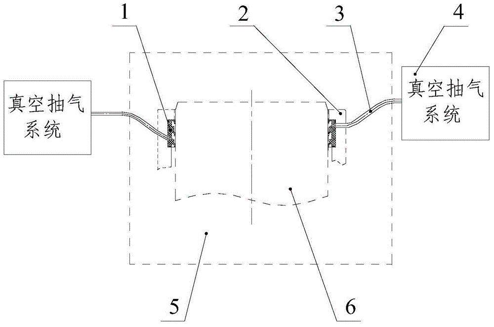
[0026] figure 1 It is a schematic diagram of the structure of the large-diameter rotary dynamic sealing system in the vacuum and low temperature environment of the present invention. The sealing system includes a sealing ring 1, a sealing flange 2, an exhaust pipe 3, a vacuum exhaust system 4, a vacuum container 5, a rotating shaft 6, and a sealing ring 1 is connected to the vacuum pumping system 4 through the pumping pipe 3 and mechanically fixedly connected through the sealing flange 2. Except for the vacuum pumping system, other components are arranged inside ...


PUM


Abstract

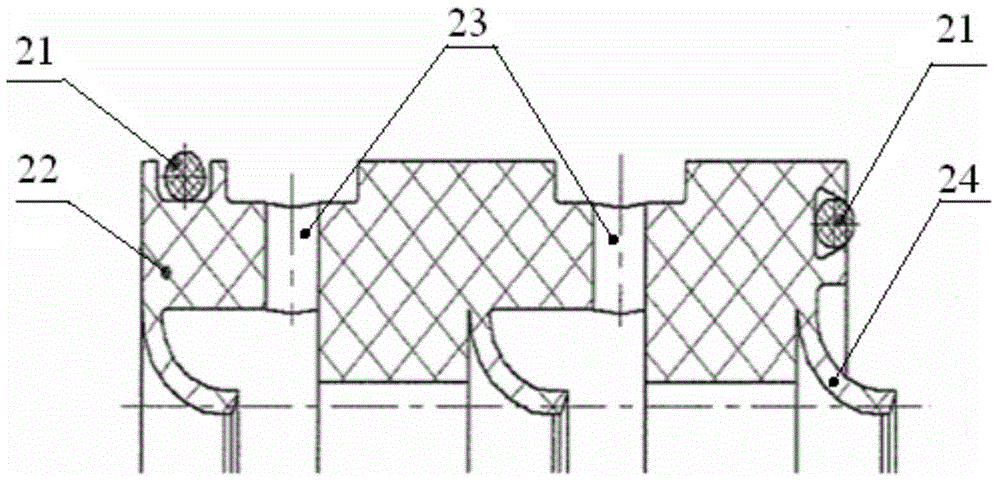
The invention discloses a dynamical sealing system with heavy caliber in vacuum and low temperature environment. The dynamical sealing system with heavy caliber in vacuum and low temperature environment comprises a dynamic sealing ring, two static sealing rings and two sets of parallel vacuum pumping system. The dynamic sealing ring comprises an one-piece three lines lip-shaped check ring. Cylindrical blank which is made by plastic material processes successively equidistant three lines lip on the lateral side of the dynamic sealing, which is equal to three lines of seal. Radical direction of the above-mentioned cylindrical blank establishes a through-hole between every two lips. Two sets of parallel vacuum pumping system which is equipped outside the vacuum container exhaust air outside the container by two through-hole between the lips and the static sealing ring is equipped on the installation surface of the dynamic sealing ring. The sealing system of the invention obviously improves the dynamical sealing effect with heavy caliber in vacuum; meanwhile the shaft installation space of the system is small and the requirements of the dynamical sealing effect with heavy caliber in vacuum can be solved in the small installation space; the deformation of lips of optimized sealing ring is large and has recovery effects, which not only make sure the sealing effects but also solve the problem that the sealing ring is worn prematurely.

Description

technical field [0001] The invention belongs to the field of space environment simulation, and in particular relates to a rotary dynamic sealing system used in a vacuum and low temperature environment. Background technique [0002] When a spacecraft uses a solar simulator for vacuum thermal testing in a vacuum container on the ground, the spacecraft is generally mounted on a motion simulator. Adjust the attitude of the spacecraft through the motion simulator, so that the spacecraft receives the irradiation of the beam of the solar simulator at different angles, so as to ensure that the angular relationship between the spacecraft and the solar beam is the same or similar to that of the in-orbit flight condition, or is the same as the overall design The external heat flow environment is the same. The large-diameter rotary dynamic sealing system (usually refers to the diameter above Φ500mm) is one of the key components of the motion simulator, which is used to meet the rotary ...

Claims


Application Information

Patent Timeline
Patent Type & Authority Applications(China)
IPC IPC(8): F16J15/32F16J15/18F16L59/08F16J15/3284
Inventor 杨林华肖庆生董雷王军伟吕世增龚洁郭峰
Owner BEIJING INST OF SPACECRAFT ENVIRONMENT ENG
Learn More