
Brushless direct-current motor simulator

A DC motor and simulator technology, applied in the direction of electronic commutation motor control, electrical components, control systems, etc., can solve the problems of equipment performance degradation, affecting flywheel safety, high price, etc., to achieve protection safety, convenient transportation, and easy operation. Effect

Active Publication Date: 2014-02-26
BEIHANG UNIV
View PDF3 Cites 8 Cited by
  • Summary
  • Abstract
  • Description
  • Claims
  • Application Information

AI Technical Summary

Problems solved by technology

If the actual system is used for experiments, it will often cause unpredictable consequences, which may seriously cause equipment performance degradation or even damage
For example, a type of inertial actuator on a spacecraft - flywheel, which is essentially a brushless DC motor, generally runs at 10,000 rpm or more, and is expensive, bulky and heavy
When the actual flywheel is used for the test, there will be the following problems: due to the difficulty in handling, it will bring a lot of inconvenience to the debugging process; there are risks such as overcurrent and overvoltage in the debugging test of the drive control circuit, which may affect the safety of the flywheel. Once the stator The burning of the coil will not only cause a large loss of manpower, material resources and financial resources, but also greatly affect the development progress due to the long processing cycle of the flywheel body; the performance evaluation of the drive control circuit requires the measurement of various state parameters during the operation of the flywheel , some parameters are difficult or even impossible to measure

Method used


Image

  • Brushless direct-current motor simulator
  • Brushless direct-current motor simulator
  • Brushless direct-current motor simulator

Examples


Embodiment

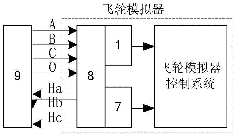
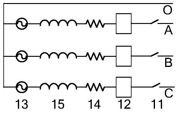
[0063] The present invention adopts TI company's DSP-TMS320F28335 with a floating-point core as the CPU to complete the relevant calculation of the motor model; use the integrated AD converter to sample the output of the current sensor; use the integrated PWM module to cooperate with low-pass filtering The device completes the DA conversion output of the back EMF control signal; uses the IO port peripheral to control the work of the relay, and cuts off the connection between the three-phase analog winding of the brushless DC motor simulator and the electrical interface when an abnormality such as overcurrent is detected; also uses the IO port peripheral Combined with the timer to control the OC gate to simulate the output of the Hall position sensor. The invention uses Honeywell's current transformer to detect the three-phase winding current, and converts it into a voltage signal output, which is processed by low-pass filtering and biasing for AD sampling. The invention adopts...


PUM


Abstract

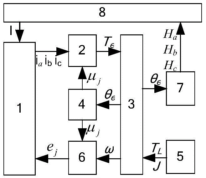
Disclosed in the invention is a brushless direct-current motor simulator. A winding subsystem simulator simulates a winding resistor, an inducer and a back electromotive force; an electromagnetic subsystem simulator simulates an electromagnetic moment of a brushless direct-current motor; a load characteristic simulator simulates a load moment; a mechanical subsystem simulator simulates a mechanical characteristic of the brushless direct-current motor; a magnetic flux density simulator simulates a distribution characteristic of the magnetic flux density of the rotor of the brushless direct-current motor; a back electromotive force subsystem simulator simulates back electromotive forces of three-phase windings of the brushless direct-current motor; and a position sensor simulator simulates an output signal of a switch hall sensor. According to the invention, the electronic load of the brushless direct-current motor body can be replaced; and the brushless direct-current motor simulator has the real electrical and mechanical characteristics of the brushless direct-current motor; important parameters like a driving voltage, a driving current, a back electromotive force and an electromagnetic moment and the like can be monitored; information including commutation errors and current abnormality and the like can be recorded; and the simulator has the fault self-diagnosis capability and the processing capability.

Description

technical field [0001] Design a brushless DC motor simulator, which can simulate the electronic load of the brushless DC motor, and has the basic characteristics of the brushless DC motor, such as damping coefficient, number of pole pairs and moment of inertia. The virtual winding of the electronic load has the same or similar electrical parameters as the actual winding, such as inductance and resistance, and can run under the drive of the driver. During the operation, it objectively reflects the basic characteristics of the brushless DC motor, such as back EMF coefficient, torque coefficient, etc. Background technique [0002] The position sensorless brushless DC motor is a new type of motor that has been produced and developed rapidly in recent years. It has the advantages of simple structure, and at the same time avoids the problems of high installation accuracy of the position sensor, many leads, reduced reliability, and limited working environment. , can be widely used ...

Claims


Application Information

Patent Timeline
Patent Type & Authority Applications(China)
IPC IPC(8): H02P6/00
Inventor 吴忠吕昊暾张健王侃
Owner BEIHANG UNIV
Learn More