
Purification system for flue gas generated in hazardous waste incineration

A technology of incineration flue gas and purification system, applied in the field of flue gas purification, can solve the problems of low safety, high investment cost, and low acid removal efficiency, and achieve the effect of improving processing capacity and reducing pollution

Active Publication Date: 2014-03-05
WUXI XUELANG ENVIRONMENTAL TECH CO LTD
View PDF7 Cites 24 Cited by
  • Summary
  • Abstract
  • Description
  • Claims
  • Application Information

AI Technical Summary

Problems solved by technology

[0003]Dry deacidification is to spray dry chemical into the flue gas, and the chemical reacts with the flue gas in the reactor to remove the acid gas. Its disadvantages The reason is that this method uses a large amount of chemicals, which leads to an increase in its use cost, and its acid removal efficiency is relatively lower than that of the semi-dry method and the wet method.
[0004] Semi-dry deacidification is to spray lime slurry into the reactor by nozzle or rotary sprayer to form droplets with small particle size, so that acid gas and lime slurry The reaction produces salts, and its disadvantage is that the preparation of lime slurry is complicated and the efficiency of acid removal is limited
[0005]The wet deacidification method adopts the form of a scrubber, which will produce wastewater containing high concentrations of inorganic chloride salts and heavy metals. It also needs to be equipped with a wastewater treatment system. The investment cost is high and the operation high cost
[0006] It can be seen that any of the above-mentioned deacidification processes has its own shortcomings, and the single use of a certain method has low safety and low reliability.
Once there is a problem, it may cause environmental pollution

Method used


Image

  • Purification system for flue gas generated in hazardous waste incineration

Examples


Embodiment Construction

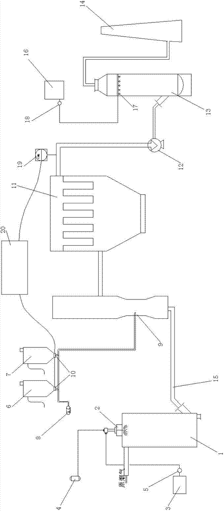
[0018] See figure 1 , which includes a quenching device 1, the quenching device 1 has a flue gas inlet and a flue gas outlet, the flue gas outlet of the quenching device 1 is connected to a flue gas purification device through a pipeline, the outlet of the flue gas purification device is connected to a chimney 14, and the flue gas purification device It specifically includes a dry reactor 5, a bag filter 11, and a wet scrubber 13. The flue gas outlet of the quenching device 1 is connected to the flue gas inlet of the dry reactor 5, and the flue gas outlet of the dry reactor 5 is connected to the bag type dust collector. The flue gas inlet of the device 11, the flue gas outlet of the bag filter 11 is connected to the flue gas inlet of the wet scrubber 13, and the flue gas outlet of the wet scrubber 13 is connected to the chimney 14. The quenching device 1 is specifically a quenching tower, the top of the quenching tower is provided with a dual-fluid spray gun 2, and the two inl...


PUM


Abstract

The invention provides a purification system for flue gas generated in hazardous waste incineration. According to the system, three deacidification filtering systems of dry dust removal, wet dust removal and cloth bag dust removal are combined; the disadvantages of the three deacidification filtering systems during the respective independent using processes are overcome; the treatment capability of acid gas in the flue gas generated by hazardous waste incineration is improved. The system comprises a quenching device, wherein the quenching device is provided with a flue gas inlet and a flue gas outlet; the flue gas outlet of the quenching device is communicated with a flue gas purification device through a pipeline; an outlet of the flue gas purification device is communicated with a chimney. The system is characterized in that the flue gas purification device specifically comprises a dry reactor, a bag dust remover and a wet washing tower, wherein the flue gas outlet of the quenching device is connected with a flue gas inlet of the dry reactor; a flue gas outlet of the dry reactor is connected with a flue gas inlet of the bag dust remover; a flue gas outlet of the bag dust remover is connected with a flue gas inlet of the wet washing tower; a flue gas outlet of the wet washing tower is communicated with the chimney.

Description

technical field [0001] The invention relates to the technical field of flue gas purification, in particular to a hazardous waste incineration flue gas purification system. Background technique [0002] At present, according to the flue gas emission standards, it is necessary to purify the acid gases (mainly HCL, HF, SO2), dust particles, dioxins, heavy metals and other pollutants in the flue gas produced by incineration of hazardous waste. In the flue gas process of hazardous waste incineration in the prior art, the acid gas is removed first, and then the dust particles are filtered. Among them, the removal method of acid gas adopts dry method, or semi-dry method, or wet method. [0003] Dry deacidification is to spray dry chemical into the flue gas, and the chemical reacts with the flue gas in the reactor to remove the acid gas. The disadvantage of this method is that the amount of chemical used in this method is large, resulting in an increase in the cost of use. , its a...

Claims


Application Information

Patent Timeline
IPC IPC(8): B01D53/75B01D53/50B01D53/68B01D50/00
Inventor 王立马文
Owner WUXI XUELANG ENVIRONMENTAL TECH CO LTD
Learn More