Impinging stream reactor

A technology of impinging flow reactors and nozzles, applied in chemical/physical/physical chemical nozzle reactors, chemical methods for reacting liquids with liquids, chemical instruments and methods, etc. The chemical reaction promotion effect is not obvious enough to achieve the effect of improving the promotion effect

Active Publication Date: 2014-03-05
EAST CHINA UNIV OF SCI & TECH +1
View PDF3 Cites 24 Cited by
  • Summary
  • Abstract
  • Description
  • Claims
  • Application Information

AI Technical Summary

Problems solved by technology

[0005] The technical problem to be solved in the present invention is to overcome the impinging flow reactor in the prior art, but the promoting effect on fluid mixing and chemical react

Method used


Image

  • Impinging stream reactor
  • Impinging stream reactor
  • Impinging stream reactor

Examples


Embodiment 1

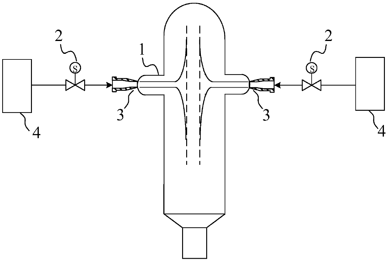
[0024] Such as figure 1 As shown, the impingement flow reactor of this embodiment includes a chamber 1, two storage tanks 4 and two nozzles 3, the two storage tanks 4 are respectively used to feed the two nozzles 3, the two A nozzle 3 is relatively arranged on the side wall of the chamber 1, and its characteristic is that the impingement flow reactor also includes a control unit and two proportional valves 2, and the control unit is used to control the direction of the two proportional valves 2 to The flow rates supplied by the two nozzles 3 are respectively adjusted to fluctuate according to a first preset waveform and a second preset waveform, wherein both the first preset waveform and the second preset waveform are periodic.

[0025] Wherein, the shape and frequency of the first preset waveform and the second preset waveform are the same, and the phase difference is π. The shapes of the first preset waveform and the second preset waveform are both square waves, the frequen...

Embodiment 2

[0033] The impingement flow reactor of the present embodiment is compared with embodiment 1, and difference only lies in:

[0034] The amplitudes of the first preset waveform and the second preset waveform are 5% of the average flow rate of the respective corresponding nozzles 3 . At the same time, the chamber 1 is also a gasifier.

[0035] A case where the impinging flow reactor of this embodiment is applied to the gasification of coal-water slurry will be described below. In this case, the materials used for the mixed reaction were 65% Shenfu coal slurry and pure oxygen. The content of each component of Shenfu coal slurry is expressed in mass percentage as follows: the moisture of the original sample is 7.17%, the ash content of the dried sample is 6.58%, the volatile matter is 39.70%, the fixed carbon is 53.72%, the carbon is 69.32%, the hydrogen is 4.72%, and the nitrogen is 0.86% %, sulfur 0.49%.

[0036]In this case, the materials received and ejected by the two nozzl...


PUM

PropertyMeasurementUnit
Densityaaaaaaaaaa
Densityaaaaaaaaaa

Abstract

The invention discloses an impinging stream reactor which comprises a chamber, two storage tanks and two nozzles, wherein the two storage tanks are respectively used for feeding materials to the two nozzles, and the two nozzles are oppositely arranged on the side wall of the chamber. The impinging stream reactor also comprises a control unit and two proportional valves, wherein the control unit is used for controlling the two proportional valves to adjust the feeding flows to the two nozzles to flocculate according to a first preset waveform and a second preset waveform respectively, and the first preset waveform and the second preset waveform both have periodicity. In the impinging reactor disclosed by the invention, by controlling the two proportional valves to adjust the feeding flows to the two nozzles to flocculate according to the preset waveforms respectively, the periodic oscillation of the impinging surface of the impinging stream is caused, so that the acceleration effect on the fluid mixing and chemical reaction of the impinging stream reactor is improved, and the impinging stream reactor can obtain an ideal mixing effect when applied to a fluid mixing reaction with low Reynolds number.

Description

technical field [0001] The present invention relates to an impingement flow reactor. Background technique [0002] The scientific concept of impinging flow was first proposed by Elperin of the former Soviet Union in 1961, and later the Israeli Tamir team conducted more applied basic research. The researchers at that time came to the conclusion that almost any process in the field of chemical engineering can be realized by impinging flow, and the impinging flow is more efficient and less energy-consuming than traditional methods; It is bound to become a common technical method in engineering and other engineering fields. As they expected, impinging flow has been rapidly and successfully applied in unit operations and industrial processes such as drying, gasification, combustion, catalytic reaction, absorption, extraction, and nanoparticle preparation in recent years, showing great potential and application prospects. [0003] Impinging flow is an important method to achieve...

Claims


Application Information

Patent Timeline
IPC IPC(8): B01J19/26B01J14/00
Inventor 李伟锋赵辉刘海峰王辅臣于广锁龚欣王亦飞许建良梁钦锋周志杰代正华陈雪莉郭晓镭王兴军郭庆华刘霞陆海峰李超龚岩王立
Owner EAST CHINA UNIV OF SCI & TECH
Why Eureka
Try Eureka