Mixed vaporizer internal combustion waste heat utilization system
An internal combustion waste heat and vaporizer technology, applied in the energy and power fields, can solve the problems of high manufacturing cost and complex structure, and achieve the effect of low manufacturing cost and simple structure
- Summary
- Abstract
- Description
- Claims
- Application Information
AI Technical Summary
Problems solved by technology
Method used
Image

Examples
Embodiment 1
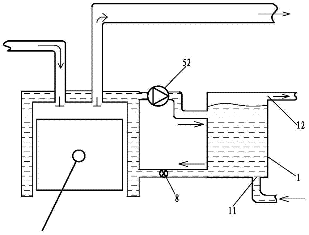
[0052] Such as figure 1 The hybrid vaporization internal combustion waste heat utilization system shown includes a hybrid vaporizer 1, the high-temperature liquid inlet of the hybrid vaporizer 1 communicates with the fluid outlet of the cooling channel of the internal combustion engine through a liquid circulation booster pump 52, and the low-temperature liquid of the hybrid vaporizer 1 The outlet communicates with the fluid inlet of the internal combustion engine cooling channel through the throttling control valve 8. A steam outlet 12 is provided on the hybrid carburetor 1, and a working medium inlet 11 is arranged on the liquid area of the hybrid carburetor 1. The hybrid carburetor 1 The pressure bearing capacity is greater than 0.3MPa.
Embodiment 2
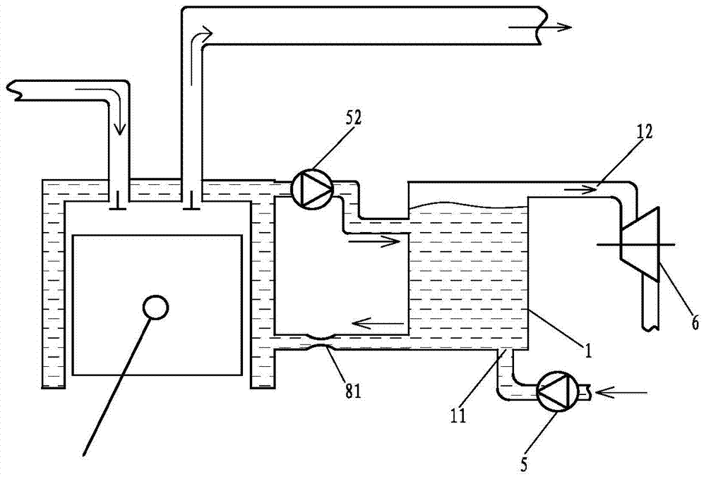
[0054] Such as figure 2 The difference of Embodiment 1 of the mixed vaporization internal combustion waste heat utilization system shown is:
[0055] The throttling control valve 8 is canceled, and a throttling structure 81 is set at the same position, and the working medium inlet 11 is further connected with the liquid outlet of the liquid pump 5, and the steam outlet 12 is connected with the working mechanism.
[0056] In this embodiment, the working mechanism is specifically set as a turbine 6, and as a convertible embodiment, the working mechanism can also be set as other forms of working mechanism, such as a cylinder-piston mechanism and the like.
[0057] As a changeable implementation manner, the working mechanism may not be provided.
Embodiment 3
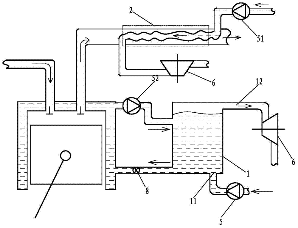
[0059] Such as image 3 The hybrid vaporization internal combustion waste heat utilization system shown, on the basis of Embodiment 1, the hybrid vaporization internal combustion waste heat utilization system further includes an exhaust heat exchanger 2, and the heated fluid channel of the exhaust heat exchanger 2 The outlet of the working medium communicates with the inlet of the working medium of the auxiliary working mechanism, the inlet of the working medium of the heated fluid channel of the exhaust heat exchanger 2 communicates with the outlet of the liquid of the auxiliary liquid pump 51, and the inlet of the working medium 11 communicates with the outlet of the liquid pump 5 The liquid outlet is connected, and the steam outlet 12 is connected with the working mechanism.
[0060] In this embodiment, the liquid pumped into the heated fluid channel of the exhaust heat exchanger 2 by the auxiliary liquid pump 51 is vaporized in the exhaust heat exchanger 2 and then enters ...
PUM
| Property | Measurement | Unit |
|---|---|---|
| Pressure endurance | aaaaa | aaaaa |
Abstract
Description
Claims
Application Information
 - R&D
- Intellectual Property
- Life Sciences
- Materials
- Tech Scout
- Unparalleled Data Quality
- Higher Quality Content
- 60% Fewer Hallucinations
Browse by: Latest US Patents, China's latest patents, Technical Efficacy Thesaurus, Application Domain, Technology Topic, Popular Technical Reports.
© 2025 PatSnap. All rights reserved.Legal|Privacy policy|Modern Slavery Act Transparency Statement|Sitemap|About US| Contact US: help@patsnap.com