Method for correcting near-field test phases of millimeter wave plane

A phase correction and millimeter wave technology, which is applied in the direction of measuring devices, measuring electrical variables, instruments, etc., can solve the problems of unsatisfactory accuracy, unable to measure antennas in the millimeter wave frequency band, and phase changes are not taken into account, so as to improve the test accuracy. Effect

Inactive Publication Date: 2014-03-05
THE 41ST INST OF CHINA ELECTRONICS TECH GRP
View PDF4 Cites 33 Cited by
  • Summary
  • Abstract
  • Description
  • Claims
  • Application Information

AI Technical Summary

Problems solved by technology

[0017] At present, the planar near-field antenna test system does not have a phase correction algorithm in the low-frequency band. Hardware equipment and high-phase-stable cables are generally used to ensure phase stability. The required accuracy, including positioning accuracy and phase drift error due to temperature increase of the cable
[0018] In the millimeter wave frequency band, the flatness comp

Method used


Image

  • Method for correcting near-field test phases of millimeter wave plane
  • Method for correcting near-field test phases of millimeter wave plane
  • Method for correcting near-field test phases of millimeter wave plane

Examples


Embodiment 1

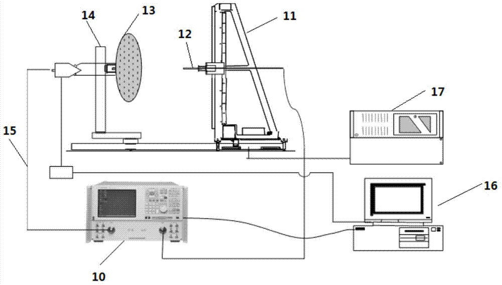
[0038] Such as figure 1 As shown, the hardware device of the present invention is mainly composed of a vector network analyzer 10, a four-axis motion scanning frame 11, a near-field probe 12, a transmitting antenna 13, a transmitting bracket 14, a main control computer 16 and the like. Wherein, the vector network analyzer 10 connects the radio frequency output port to the transmitting antenna 13 through the radio frequency cable 15, the receiving port connects the receiving probe 12 on the scanning frame 11 through the radio frequency cable, and the main control computer 16 controls the vector through the local area network or the external network through the control software. Equipment such as network analyzer 10 and scanning frame 11 carry out coordinated work, also includes position adjustment controller 17 to control scanning frame 11 test principle flow chart as figure 2 Shown: figure 2 middle,

[0039] When the near-field probe performs a two-dimensional surface scan...

Embodiment 2

[0047] On the basis of the above-mentioned embodiments, further, a millimeter-wave planar near-field test phase correction method, which includes the following steps:

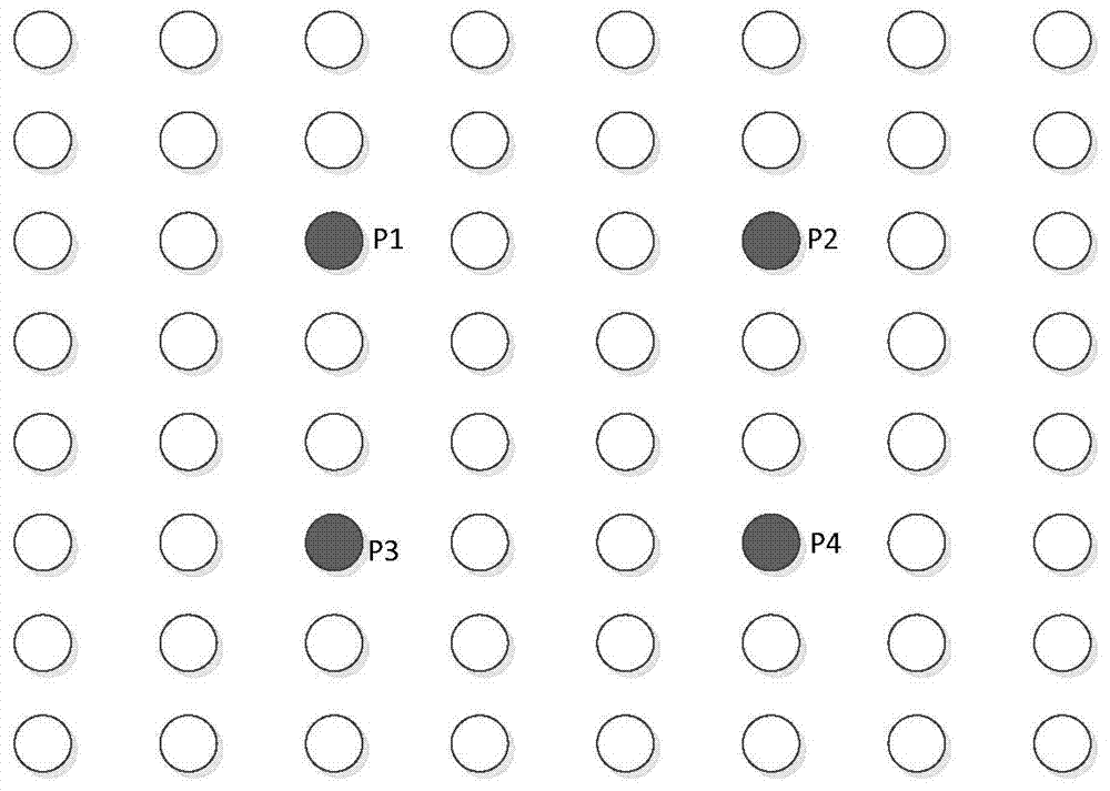
[0048] Step 1: Carry out plane scanning on the set XY plane, and select four points in the strong signal area as phase sampling points;

[0049] Step 2: Set a predetermined cycle to scan the above four points, and determine the collection time, data collection and collection position of the four points in each cycle;

[0050] Step 3: Perform phase correction on each point in the scanning surface by changing the data variation of the selected four points; where the correction formula is:

[0051] D[i,j]=A[i,j]*B[i,j]i=1,2…n,j=1,2…n; Among them, D is the corrected data; A is the collected data; B is the correction data; i is the number of points collected on the X axis; j is the number of points collected on the Y axis; n is the number of points collected;

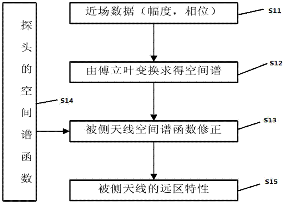
[0052] Step 4: Perform Fourier transform on the corre...


PUM


Abstract

The invention provides a method for correcting near-field test phases of a millimeter wave plane. The method comprises the steps that step 1, a set XY plane is scanned and four points in a zone with strong signals are selected to serve as phase sampling points; step 2, preset periods are set, plane scanning is conducted on the four points, and collection moments, collection data and collection positions of the four points in each period are determined; step 3, according to data variable quantity of the selected four points, the phase of each point in the scanned plane is corrected; step 4, Fourier transform is conducted on the corrected data of the whole scanned plane, far-field data are calculated through near-field data, and the near-field far-field transformation formula is . According to the technical scheme, a function relationship, corresponding to the sampling points, of phase drift and time is established through the method that the positions of the appointed sampling points on the scanned plane and the sampling data in the positions are recorded, phase compensation of the data of the whole scanned plane is achieved through the interpolation mode, and therefore the measurement accuracy of a near-field measurement system under a millimeter wave frequency band is improved.

Description

technical field [0001] The invention belongs to the technical field of near-field testing, and in particular relates to a phase correction method for millimeter-wave plane near-field testing. Background technique [0002] Since the invention of the antenna, its application in communication, radar and national defense has been increasing day by day, becoming an indispensable part of wireless equipment. The accuracy of the antenna performance affects the performance of the entire system. Antenna measurement has become an indispensable step in the antenna design process, and it is one of the important research topics. [0003] Antenna measurement comes along with the design of the antenna, and it is the guidance of the antenna design and the test verification of the performance. Whether the measurement method is accurate or not is directly related to whether the supporting system is practical or not. With the development of national defense and information industry, the requ...

Claims


Application Information

Patent Timeline
IPC IPC(8): G01R29/10G01R35/00
Inventor 赵锐王亚海杜刘革常庆功殷志军张文涛
Owner THE 41ST INST OF CHINA ELECTRONICS TECH GRP
Why Eureka
Try Eureka