Modeling method on basis of effective duty cycle for phase-shifted full-bridge ZVS (zero voltage switching) converter

A phase-shifting full-bridge, modeling method technology, applied in high-efficiency power electronic conversion, output power conversion devices, DC power input conversion to DC power output, etc., can solve the difficulty of modeling work, circuit structure and working process. Complex problems, to achieve accurate establishment, improve model accuracy, and simplify the modeling process.

Inactive Publication Date: 2014-03-05
HEFEI UNIV OF TECH
View PDF8 Cites 17 Cited by
  • Summary
  • Abstract
  • Description
  • Claims
  • Application Information

AI Technical Summary

Problems solved by technology

[0004] Compared with the hard-switching converter, the number of components of the soft-switching converter has increased, and there are various operating states including resonance (taking the phase-shifted full-bridge ZVS converter as an example, there are 12 operating states in one cycle. state), the circuit structure and working process are more complex
Therefore, in-depth modeling and analysis of soft-switching converters is an indispensable content in the design process; at the same time, these characteristics of soft-switching also make traditional modeling methods such as state-space averaging methods no longer applicable. Modeling Work Adds Difficulty

Method used


Image

  • Modeling method on basis of effective duty cycle for phase-shifted full-bridge ZVS (zero voltage switching) converter
  • Modeling method on basis of effective duty cycle for phase-shifted full-bridge ZVS (zero voltage switching) converter
  • Modeling method on basis of effective duty cycle for phase-shifted full-bridge ZVS (zero voltage switching) converter

Examples


Embodiment Construction

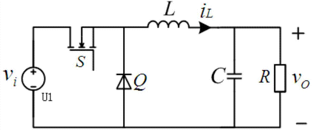
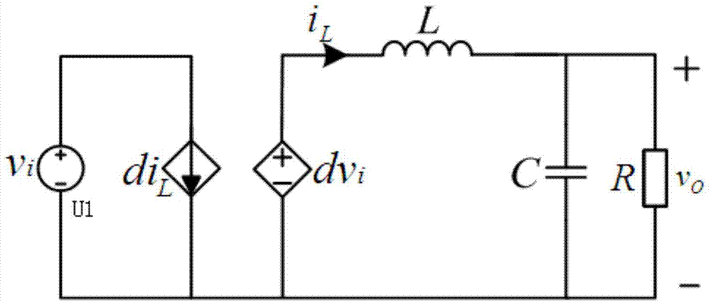
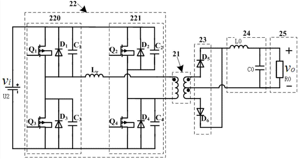
[0020] Such as figure 1 , 2 , 3, and 4, a modeling method for a phase-shifted full-bridge ZVS converter based on an effective duty cycle includes the following steps:

[0021] (1) Establish the average linear model of the Buck converter: the Buck converter is composed of an input voltage source U1, a power switching device S, a diode Q, an energy storage inductor L, a filter capacitor C and a load resistor R; the power switching device S One end is connected to the positive pole of the input voltage source U1, and the other end is simultaneously connected to the negative pole of the diode Q and one end of the energy storage inductor L; the other end of the energy storage inductor L is connected to the filter capacitor C; the other end of the filter capacitor C is simultaneously connected to the negative pole of the input voltage source U1 and The positive pole of diode Q; the load resistor R is connected in parallel with the filter capacitor C; the different states caused by ...


PUM


Abstract

The invention discloses a modeling method on the basis of an effective duty cycle for a phase-shifted full-bridge ZVS (zero voltage switching) converter. The modeling method includes steps that an average linear model of a Buck converter is built; the effective duty cycle is introduced, working procedures of the phase-shifted full-bridge ZVS converter are analyzed, and an expression of the effective duty cycle of the phase-shifted full-bridge ZVS converter is derived; a duty cycle represents a time proportion of a conducting state of each power switch in a period, the duty cycle in the Buck converter model is replaced by the effective duty cycle, input voltages of the model are represented by voltages v/n of a secondary side of a transformer of the phase-shifted full-bridge ZVS converter, and the voltages v/n are translated from input voltages v of the phase-shifted full-bridge ZVS converter, so that a phase-shifted full-bridge ZVS converter model can be obtained. The modeling method has the advantages that influence of resonance states of the phase-shifted full-bridge ZVS converter is sufficiently considered in the effective duty cycle, so that the precision of the phase-shifted full-bridge ZVS converter model can be improved, and the modeling method is also applicable to building models of other Buck soft-switching converters.

Description

technical field [0001] The invention relates to a modeling method for a phase-shifting full-bridge ZVS converter, in particular to a modeling method for a phase-shifting full-bridge ZVS converter based on an effective duty ratio, and belongs to the technical field of power electronics. Background technique [0002] In order to overcome various problems caused by DC-DC switching converters working in the hard switching state, soft switching technology came into being. It introduces an auxiliary resonant circuit to reduce switching losses, improve conversion efficiency and improve electromagnetic interference. The phase-shifted full-bridge ZVS converter is a soft-switching structure that has been widely used in recent years. [0003] As a nonlinear time-varying system, the DC-DC switching converter cannot directly use classical linear analysis methods such as Laplace transform. design. [0004] Compared with the hard-switching converter, the number of components of the soft-...

Claims


Application Information

Patent Timeline
Patent Type & Authority Applications(China)
IPC IPC(8): G06F17/50H02M3/335
CPCY02B70/1491Y02B70/10
Inventor 程心解光军
Owner HEFEI UNIV OF TECH
Why Eureka
Try Eureka