
Rectifier of alternating-current generator for vehicle

A technology of alternator and rectifier, which is applied in the direction of circuit device, battery circuit device, irreversible AC power input conversion to DC power output, etc. It can solve the problem of large forward voltage drop of PN junction diode, limit of output current, and output Voltage cannot rise and other problems, to reduce power loss, increase output current, and solve the effect of thermal runaway

Inactive Publication Date: 2014-03-12
MITSUBISHI ELECTRIC CORP
View PDF7 Cites 0 Cited by
  • Summary
  • Abstract
  • Description
  • Claims
  • Application Information

AI Technical Summary

Problems solved by technology

[0006] In such a PN junction diode, the forward voltage drop against the forward current is large, so the output voltage cannot rise, and there is a limit to the output current
[0007] In addition, there is a problem that the forward voltage drop of the PN junction diode is large, and heat generation due to power loss is large, so that the temperature of the armature winding 101 of the alternator becomes high, and the output current is suppressed.

Method used


Image

  • Rectifier of alternating-current generator for vehicle
  • Rectifier of alternating-current generator for vehicle
  • Rectifier of alternating-current generator for vehicle

Examples


Embodiment approach 1

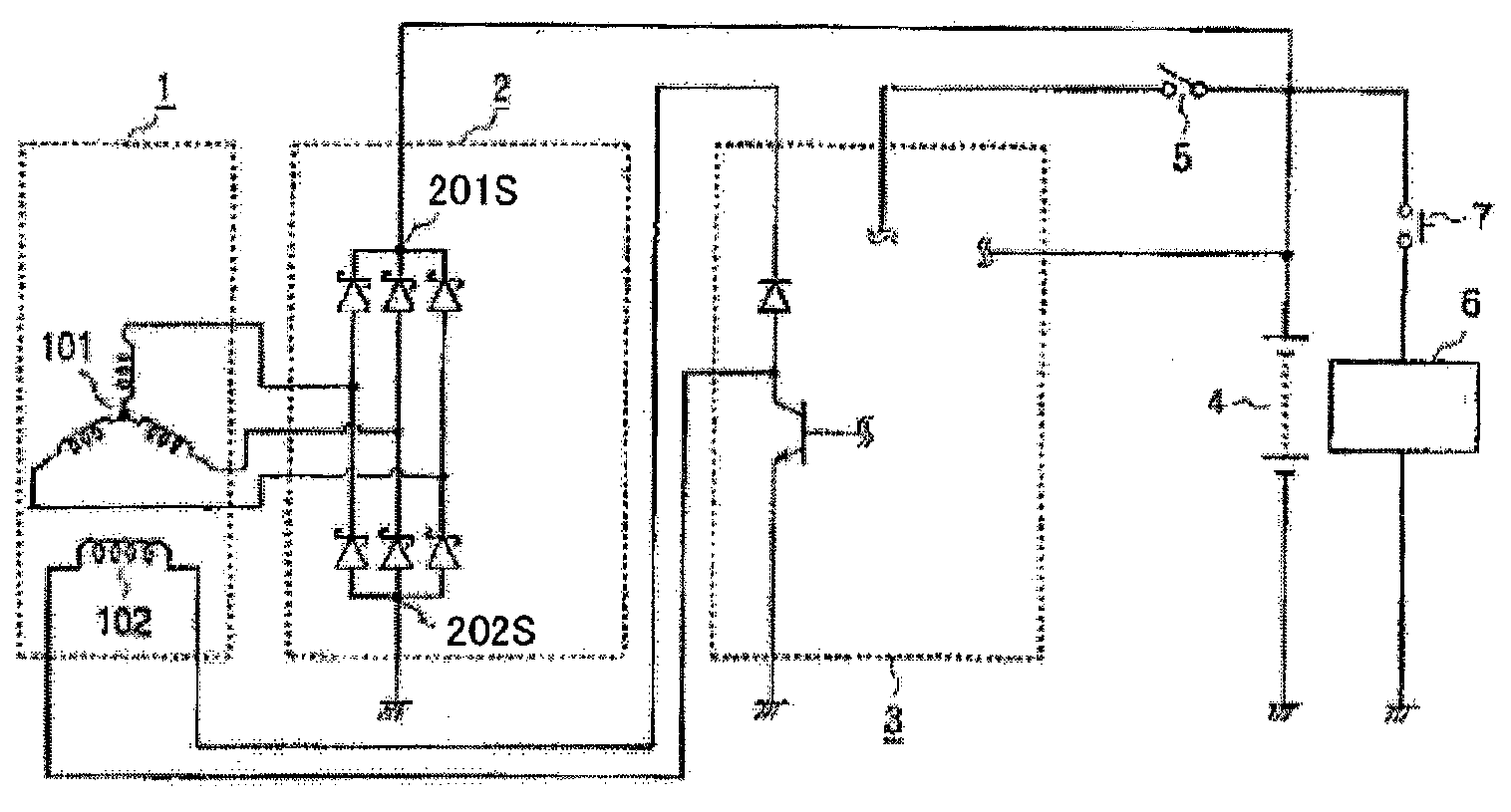
[0027] figure 1 It is a circuit configuration diagram showing a rectifier device for an automotive alternator according to Embodiment 1 of the present invention. Embodiment 1 and the above image 3 The difference in the structure of the existing device is that the diodes 201S, 202S are used instead of the PN junction diodes 201, 202 as the semiconductor elements of the rectifier 2, and the diodes 201S, 202S have positive The voltage drop to the direction is small, and the reverse leakage current is at the same level as that of the PN junction diode. Other structures are the same as image 3 same.

[0028] which is, figure 1 Among them, the rectifier device of a vehicle alternator includes: an alternator 1 including an excitation coil 102 driven by an unshown vehicle engine (engine equipment) to generate a rotating magnetic field and utilizing the generated rotating magnetic field The armature winding 101 for generating and outputting an AC voltage; the rectifier 2, which i...


PUM


Abstract

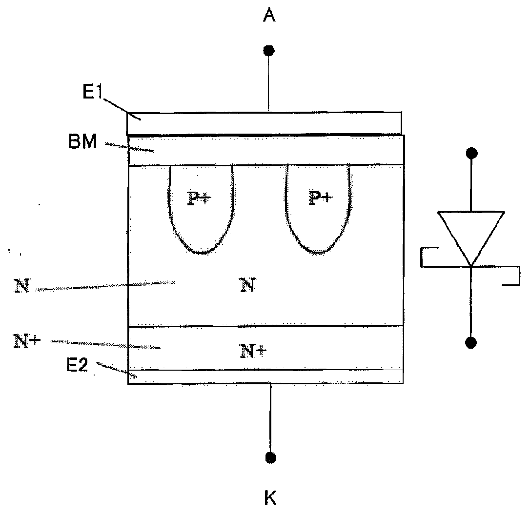
A rectifier (2) for full-wave rectification of an output of an alternating-current generator (1) for a vehicle, wherein Schottky barrier diodes are used as constituent rectifying semiconductor devices (201, 202) of the rectifier (2), said Schottky barrier diodes having the characteristics of a low forward voltage drop for a forward current and a low reverse leakage current.

Description

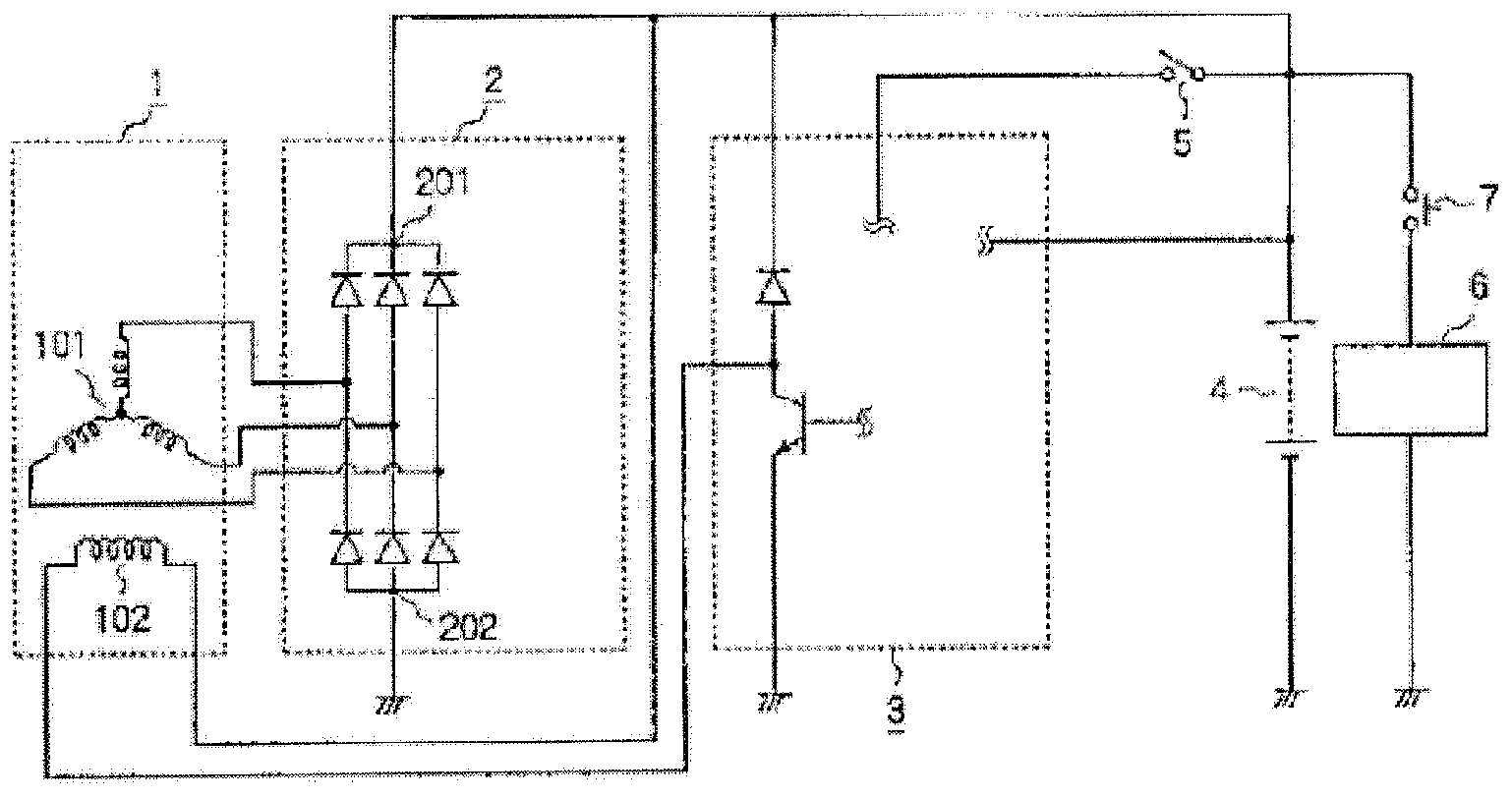
technical field [0001] The present invention relates to a rectifier device in an alternator mounted on a vehicle, and more particularly to a rectifier device for an automotive alternator using a Schottky barrier diode as a semiconductor element constituting the rectifier device. Background technique [0002] image 3 It is a circuit configuration diagram showing an example of a conventional rectifier device for an automotive alternator. [0003] A conventional rectifying device for an automotive alternator includes: an alternator 1 including an excitation coil 102 driven by a vehicle engine (engine equipment) not shown in the figure to generate a rotating magnetic field; The armature winding 101 that generates and outputs an AC voltage through a magnetic field; the rectifier 2, which rectifies the generated voltage of the alternator 1 and provides it to the battery 4 or an electric load 6 through the main terminal; the voltage regulator 3, which The voltage regulator 3 cont...

Claims


Application Information

Patent Timeline
Patent Type & Authority Applications(China)
IPC IPC(8): H02M7/06
CPCH01L29/872H02J7/16H02M7/06H01L29/861H01L29/0619
Inventor 今川清作
Owner MITSUBISHI ELECTRIC CORP
Learn More