Fiber jetting device

A spraying device and fiber technology, applied in fiber processing, textiles and papermaking, filament/thread forming, etc., can solve problems such as low spinning efficiency and easy clogging of spinnerets, so as to overcome low spinning output and avoid nozzles Easy clogging, uniform preparation effect

Active Publication Date: 2014-03-26
XIAMEN UNIV
View PDF7 Cites 18 Cited by
  • Summary
  • Abstract
  • Description
  • Claims
  • Application Information

AI Technical Summary

Problems solved by technology

[0005] The purpose of the present invention is to provide a fiber injection device that can prepare nanofibers quickly and uniformly, and solve the problems of low spinning efficiency and easy blockage of the spinneret caused by using the needle as the spinneret.

Method used


Image

  • Fiber jetting device
  • Fiber jetting device

Examples


Embodiment 1

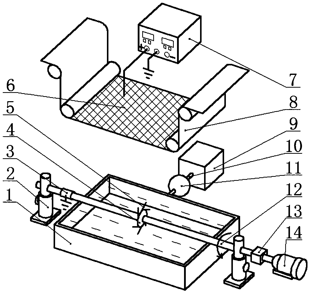
[0026] This embodiment adopts a group of spinnerets, and the assembly relationship is as follows:

[0027] The runner 4 and the rotating shaft 12 are located directly above the solution tank 1, and the plane where the runner 4 is located is perpendicular to the plane where the solution is located; 6 ropes 5 are evenly distributed on the edge of the runner 4, and the distance between adjacent ropes 5 on the circumference The angle is 60°, wherein the runner 4 and the rope 5 form the spinneret; the runner 4 is installed on the rotating shaft 12, and the rotating shaft 12 is the center of rotation; the rotating shaft 12 is connected with the driving motor 14 and the coupling 13 Connected and fixed by the lifting platform 2, the relative position of the runner 4 and the solution tank 1 can be adjusted by using the lifting platform 2, thereby changing the length of the rope 5 immersed in the solution, and fibers with different shapes, orientations and diameters can be obtained; The...

Embodiment 2

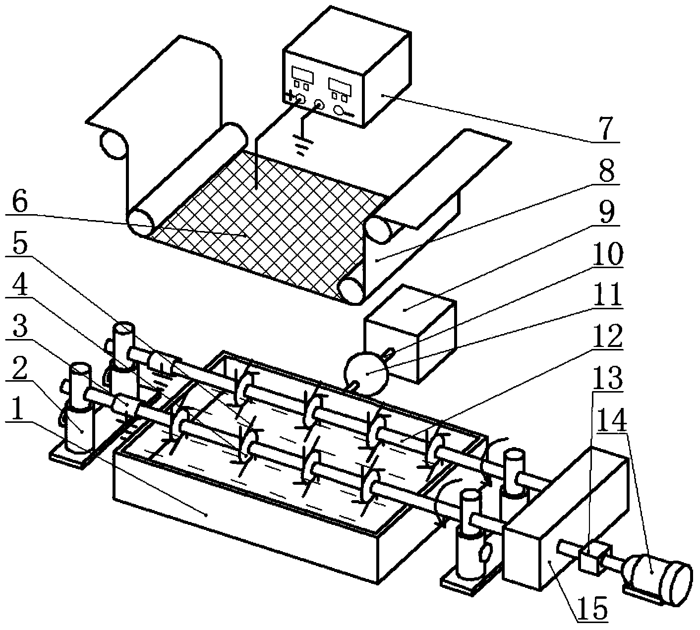
[0038] This example figure 2 As shown, multiple groups of spinnerets arranged in parallel arrays along the rotating shafts 12 are provided with a plurality of rotating shafts 12 arranged side by side, which can realize batch production of nanofibers with multiple rotating shafts 12 . A multi-axis output box 15 is provided between the drive motor 14 and the multiple rotating shafts 12 to meet the requirement that the same power drives multiple rotating shafts 12 to work simultaneously.

[0039] The remaining mechanical structures and connections are the same as in Embodiment 1.

[0040] This embodiment can further improve the efficiency of electrospinning and realize the large-scale production of nanofibers.


PUM


Abstract

The invention discloses a fiber jetting device, and relates to a fiber manufacturing device. The device is provided with a rotary wheel, a throwing rope, a rotary shaft, a solution tank, a driving motor, a lifting platform, an electric brush, a liquid storage box, a liquid supplying pipe, a metering pump, a coupler, a fiber collecting and conveying device, a high-voltage electrode net, a high-voltage power source and a control circuit. Electrostatic spinning liquid feeding is performed through the throwing rope, the defects that in a needle head type electrostatic spinning technology, a sprayer is blocked easily, the device is difficult to clean, the spinning efficiency is low and the spinning quality is poor are avoided, and meanwhile electric field interference phenomena such as the fringe effect happening in the multi-sprayer electrostatic spinning process are avoided. By changing the material, the diameter, the length and the shape of the cross section of the throwing rope, the shape, the arrangement and the output of fibers can be controlled. Further, by controlling the immersion length of the throwing rope, the rotation speed of the rotary wheel, the distance between the rotary wheel and the fiber collecting and conveying device, the electric field intensity and other electric spinning technological parameters, the electrostatic spinning efficiency and the quality of the fibers are improved, the nanometer fibers can be manufactured fast and evenly, and large-scale industrial production of the nanometer fibers is facilitated.

Description

technical field [0001] The invention relates to a fiber manufacturing device, in particular to a fiber jetting device. Background technique [0002] Electrospinning technology is a commonly used technology for producing nanofibers. It has become a hot spot in the current research on nanofiber manufacturing due to its excellent characteristics such as simple equipment and easy operation. The process principle of traditional electrospinning technology is that the polymer solution or melt is placed in a high-voltage electrostatic field, and the charged droplets or molten droplets form Taylor cones. When the electric field force is large enough, the droplets or melt can overcome the surface tension. The bondage of the jet forms a jet and sprays from the tip of the Taylor cone. The jet is continuously stretched and refined by the electrostatic field force, viscous resistance, surface tension, etc., and is solidified by solvent volatilization or melt cooling, and finally falls on ...

Claims


Application Information

Patent Timeline
Patent Type & Authority Applications(China)
IPC IPC(8): D01D5/00
Inventor 郑高峰王伟庄明凤周如海余兆杰孙道恒
Owner XIAMEN UNIV
Why Eureka
Try Eureka