Centrifugal compressors for exhaust gas turbochargers

A technology for centrifugal compressors and exhaust gas turbines, which is applied to gas turbine devices, parts of pumping devices for elastic fluids, machines/engines, etc., and can solve the problem of reduced compressor wheel transfer rate and reduced performance of exhaust gas turbochargers, etc. problem, to achieve the effect of avoiding movement

Active Publication Date: 2017-12-01
BMTS TECH SHANGHAI CO LTD
View PDF6 Cites 0 Cited by
  • Summary
  • Abstract
  • Description
  • Claims
  • Application Information

AI Technical Summary

Problems solved by technology

However, if the gap is too large, that is, the width of the gap is too large, the performance of the exhaust gas turbocharger using the compressor wheel will be reduced, because the gap causes a decrease in the compressor wheel transfer rate.

Method used


Image

  • Centrifugal compressors for exhaust gas turbochargers

Examples


Embodiment Construction

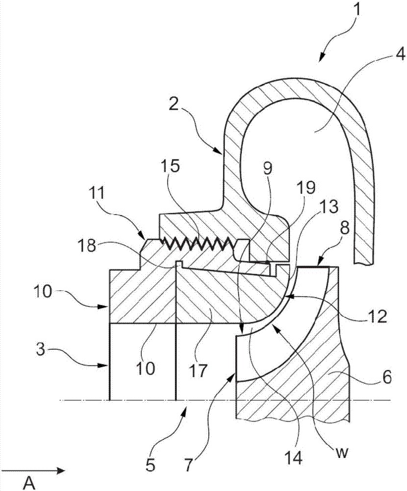
[0027] figure 1 A centrifugal compressor for an exhaust gas turbocharger according to the invention is shown, denoted by reference numeral 1 . The centrifugal compressor 1 comprises a compressor housing 2 with an axial inlet passage 3 and a centrifugal discharge passage 4 . The compressor housing 2 partially surrounds a compression space 5 . In the compression space 5 is arranged a compressor wheel 6 for conveying and compressing the gas. The compressor wheel 6 comprises an axial intake side 7 towards the intake channel 3 and a centrifugal discharge side 8 towards the exhaust channel 4 . The axial wheel surface profile 9 extends from the intake side 7 to the exhaust side 8 .

[0028] The centrifugal compressor 1 further comprises an adapter 10 generally in the form of a sleeve. The adapter 10 can be inserted along the axial direction A around the axial inlet passage 3 into a fixing section 11 provided on the compressor housing 2 . At a first end 12 facing the compressor wh...


PUM


Abstract

The compressor (1) has a sleeve-like adapter element (10) sectionally including a surface contour (13) at an axial front side (12), which faces towards a compressor wheel (6) in an axial fixing position. The surface contour is formed complementary to an axial wheel-surface contour (9) so that a width (w) of a passage gap (14) is adjusted by axially moving an adapter element in a fastening section (11) in a non-fixed condition of the adapter element. The gap is axially formed between the adapter element and the compressor wheel along the surface contours facing towards each other. The adapter element is made of a plastic material. Independent claims are also included for the following: (1) a turbocharger (2) a method for manufacturing a radial compressor.

Description

technical field [0001] The present application relates to a centrifugal compressor for an exhaust gas turbocharger, in particular for an exhaust gas turbocharger of an internal combustion engine, and to an exhaust gas turbocharger having such a centrifugal compressor. The invention also relates to a method of producing such a centrifugal compressor. Background technique [0002] Exhaust turbochargers are used, for example, in internal combustion engines to increase the pressure during gas exchange. Such an exhaust gas turbocharger can be provided with a centrifugal compressor having a compressor wheel through which gas can flow and be compressed. For this purpose, the compressor wheel can comprise an axial inlet side and a radial outlet side and be arranged in the compression space. An intake channel leads to the inlet side of the compressor wheel and, for internal combustion engines, to the low-pressure area of ​​the fresh air system equipped with the exhaust gas turbocha...

Claims


Application Information

Patent Timeline
Patent Type & Authority Patents(China)
IPC IPC(8): F04D29/42F04D29/28
CPCF01D9/026F01D25/24F02C6/12F04D25/024F04D29/4213F04D29/622F05D2220/40F05D2260/30Y10T29/49243
Inventor 马克思·菲德勒乌尔斯·黑尼希法比安·哈斯林格
Owner BMTS TECH SHANGHAI CO LTD
Why Eureka
Try Eureka