Cryogenic Butterfly Valve with Composite Dispersion Disc Bonnet

A heat dissipation plate and valve cover technology, applied in valve heating/cooling devices, valve lifts, valve details, etc., can solve the problems of small convection area between cold temperature and ambient temperature, insufficient sealing specific pressure, frequent replacement, etc. To avoid scratching the valve stem and packing, to ensure the opening and closing action of the valve, and to prevent the effect of freezing and sticking

Active Publication Date: 2015-11-18
HUBEI TAIHE PETROCHEM EQUIP
View PDF6 Cites 1 Cited by
  • Summary
  • Abstract
  • Description
  • Claims
  • Application Information

AI Technical Summary

Problems solved by technology

However, in the existing technology, the bonnet of the cryogenic top-mounted butterfly valve adopts a single large-diameter cooling plate and an extended bonnet top to dissipate temperature, but the radius of the single cooling plate increases, and the closer to the periphery, the cryogenic medium The smaller the temperature difference between the cold temperature transmitted by the base surface and the ambient convection, that is to say, the average temperature conductivity is reduced, the cooling conditions are not sufficient, and the effect is poor; it is necessary to extend the top of the valve cover, but the cold temperature of the peripheral wall of the top is extended The area for heat dissipation and convection with the environment is small, and the heat dissipation conditions are not good enough, which will reduce the strength of the valve cover and increase the cost
Insufficient heat dissipation conditions will cause the sliding joint between the valve stem and the packing to freeze and bond, the opening and closing action torque is large or cannot be moved, and the frozen hard objects scratch the valve stem and packing, the service life of the cryogenic butterfly valve is short, and the replacement is frequent
[0003] In addition, the sealing pair of the inner part of the butterfly valve needs to be replaced after it wears out and loses its sealing function. Since the processing size of the new replacement part will always be different from the original part, it is difficult to adjust the sealing specific pressure after replacement, and the sealing specific pressure may be insufficient or even unable to seal.
will cause leakage

Method used


Image

  • Cryogenic Butterfly Valve with Composite Dispersion Disc Bonnet
  • Cryogenic Butterfly Valve with Composite Dispersion Disc Bonnet

Examples


Embodiment Construction

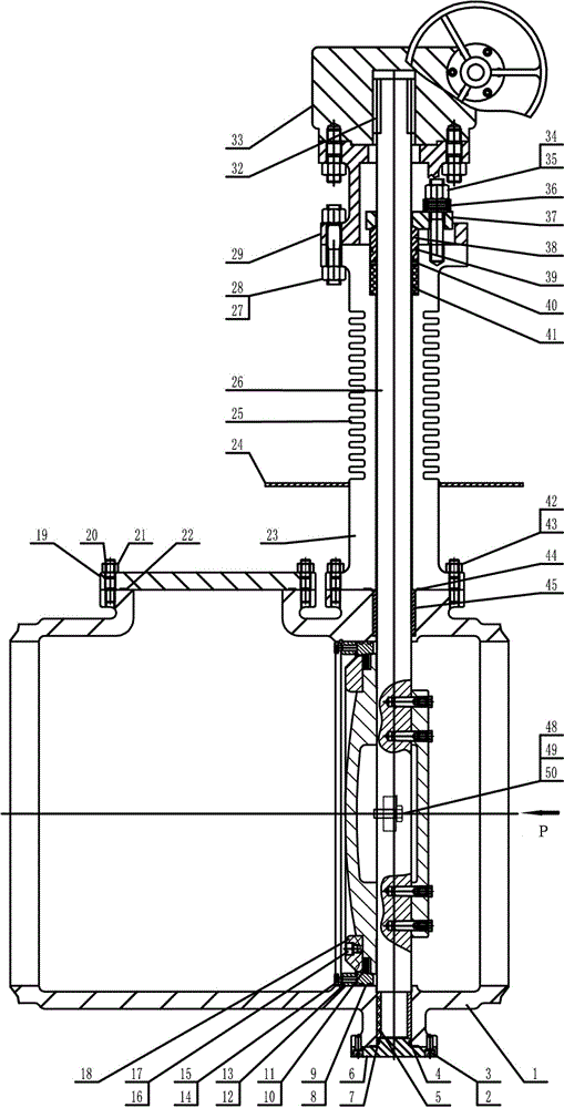
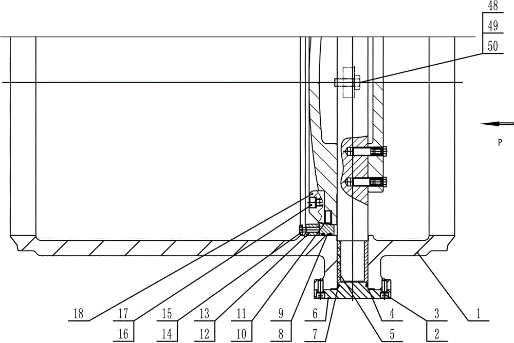
[0028] See attached Figure 1-2 As shown, a composite cooling disc bonnet cryogenic butterfly valve includes a valve body 1 in which a butterfly plate assembly and an axial floating valve seat assembly are formed, and the butterfly plate assembly and the axial floating valve seat assembly are formed Sealing structure, the valve stem 26 passes through the butterfly plate assembly and is fixed with the butterfly plate assembly, passes through the upper and lower shaft holes of the valve body, passes upwards through the bonnet 23, and connects with the graphite packing layer 41 in the upper sealing box of the bonnet. The actuator assembly 33, which extends upward through the bracket 29, drives the butterfly plate assembly by rotating 90°; the graphite packing is provided with a packing pressure sleeve 38 above the graphite packing. There is a packing gland 37 on the top, and the packing gland is fixedly connected with the valve cover; the outside of the valve cover is provided wit...


PUM


Abstract

Disclosed is a cryogenic butterfly valve with a composite heat dissipation disc valve cover. The cryogenic butterfly valve comprises a valve body. A butterfly plate assembly and an axial floating type valve seat assembly are arranged in the valve body and form a sealing structure. A valve rod penetrates through the butterfly plate assembly to be fixed to the butterfly plate assembly, penetrates through an upper shaft hole and a lower shaft hole of the valve body, then penetrates through the valve cover upwards, stretches outwards in cooperation with a graphite packing layer in a stuffing box on the upper portion of the valve cover, and stretches upwards until penetrating through a support and entering an actuator assembly above the support. The actuator assembly does 90-deree rotary motion to drive the butterfly assembly to move. Due to the adoption of the thinking of improving temperature conductivity lambda, increasing the convection heat dissipation area A of the valve cover and the surrounding environment and the convection heat dissipation temperature difference delta T of the valve cover and the surrounding environment, a composite heat dissipation disc structure composed of a single large-diameter heat dissipation disc and a neck multi-ring small-diameter heat dissipation disc outside the valve cover is designed, and an excellent heat dissipation effect is achieved.

Description

Technical field [0001] The invention relates to a deep-cooling butterfly valve, in particular to a deep-cooling top-mounted butterfly valve with a composite diffuser disc valve cover. Background technique [0002] Cryogenic top-mounted butterfly valves play a very important role in the automatic control of the process of modern liquefied natural gas, liquid oxygen, liquid hydrogen, liquid helium, etc. in the cryogenic conditions of -150℃ to -250℃, and can be maintained online . In this process control, it is necessary to adjust and open and close the flow parameters of the medium according to real-time data signals. The sensitivity and reliability of its control action, the sealing performance between the valve stem and the packing, and the life are crucial. Because the lower part of the valve stem of the deep-cooled top-mounted butterfly valve bonnet is connected with the butterfly plate, the upper part is flexibly extended with the graphite packing in the sealing box, and the...

Claims


Application Information

Patent Timeline
Patent Type & Authority Patents(China)
IPC IPC(8): F16K49/00F16K41/02F16K1/36F16K1/42F16K27/02
CPCF16K1/22F16K1/222F16K1/2261F16K1/2268F16K1/42F16K27/0218F16K27/08F16K49/00
Inventor 阳学明章文忠
Owner HUBEI TAIHE PETROCHEM EQUIP
Why Eureka
Try Eureka