Sample-injection and transferring device for microporous plate

A technology of transfer device and micro-orifice plate, which is applied in the direction of analyzing materials and instruments, can solve the problems of low work efficiency, easy scattering of reagents and samples, and high production cost, and achieve the effect of simple structure, reduced production cost and difficult control

Active Publication Date: 2014-03-26
深圳徳夏生物医学工程有限公司
View PDF5 Cites 14 Cited by
  • Summary
  • Abstract
  • Description
  • Claims
  • Application Information

AI Technical Summary

Problems solved by technology

In the prior art, the transfer of microplates is generally carried out by manual transfer or robotic transfer. For manual transfer, manual on-duty is required, and the work efficiency is low. For robotic transfer, an independent three-axis system and a set of In the whole test process, an independent three-axis system is also required for the sample loading operation. Therefore, in the current situation in the industry, at least two sets of three-axis systems and A set of mechanical finger system, at the same time, needs to be equipped with multiple motion systems, motion arms, and multiple automatic sensing devices, which leads to complex system structure and automatic control, and also leads to high production costs
In addition, the two sets of three-axis systems are prone to problems such as mechanical collisions. After collisions, the reagents and samples in the microplate are easy to scatter and cause cross-contamination.

Method used


Image

  • Sample-injection and transferring device for microporous plate
  • Sample-injection and transferring device for microporous plate
  • Sample-injection and transferring device for microporous plate

Examples


Embodiment Construction

[0036] The technical solution of the present invention will be described in detail below in conjunction with the accompanying drawings and specific embodiments, so as to understand the essence of the present invention more clearly and intuitively.

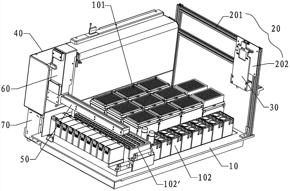
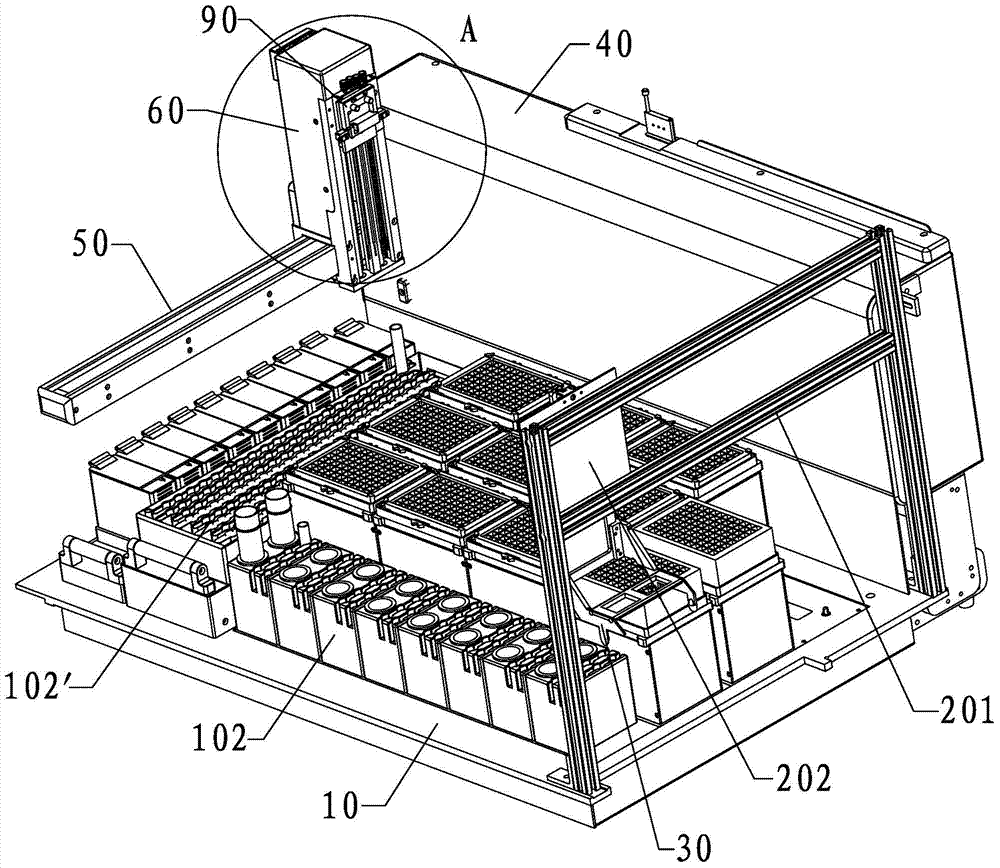
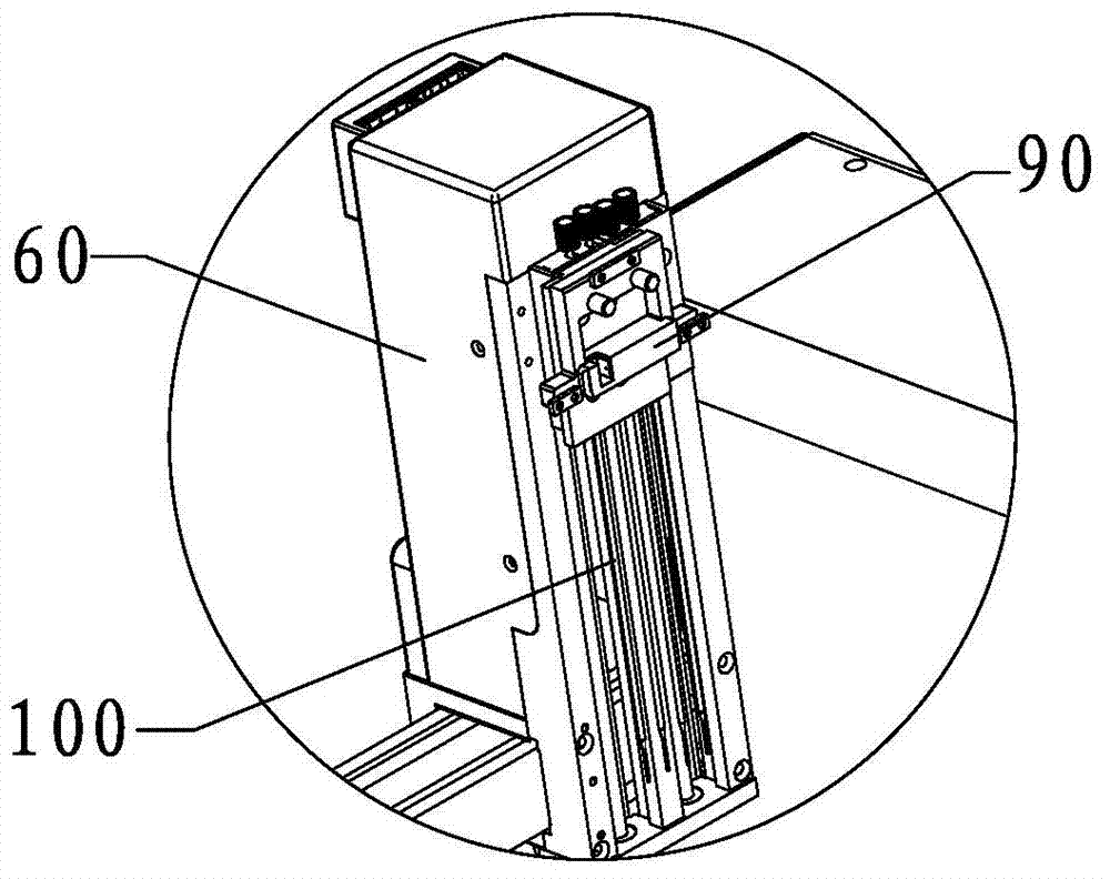
[0037] Such as Figure 1 to Figure 7 As shown, the present invention provides a microplate sampling and transfer device, which includes a workbench 10, a gripper placement mechanism 20, a microplate gripper mechanism 30, a three-axis motion mechanism and a control system, wherein the workbench Sample rack 102, 102' and microporous plate 101 are placed on the 10, various samples or other test solutions are housed in the sample rack 102, 102', the micropore plate 101 has a plurality of holes, and the The samples and / or other test solutions in the sample racks 102, 102' are added to the wells on the microwell plate 101, and then the microwell plate 101 is transferred to the test equipment 80 (enzyme immunoassay analyzer, chemiluminesc...


PUM


Abstract

The invention discloses a sample-injection and transferring device for a microporous plate. The sample-injection and transferring device comprises a workbench, a tongs arrangement mechanism, a microporous plate tongs mechanism, a triaxial motion mechanism and a control system, wherein the tongs arrangement mechanism is arranged on one side of the workbench; a hanging structure and a butting fixing structure are arranged on the microporous plate tongs mechanism; the triaxial motion mechanism is arranged above the workbench and comprises an X-axis motion mechanism, a Y-axis motion mechanism and a Z-axis motion mechanism; a moving arm is arranged on the Z-axis motion mechanism; a sample injection needle for taking a sample from a sample frame and injecting the sample into the microporous plate and a tongs seat for mounting and fixing the microporous plate tongs mechanism are arranged on the moving arm. Through the adoption of the triaxial motion mechanism and the microporous plate tongs mechanism, the sample-injection and transferring device disclosed by the invention realizes the functions of sample injection, microporous plate grabbing and transferring and the like in a test process are realized; compared with the conventional sample-injection and transferring device with two triaxial systems and a mechanical finger system in the prior art, the sample-injection and transferring device disclosed by the invention is simpler in structure, and the production cost and the control difficulty are greatly reduced.

Description

technical field [0001] The invention relates to the technical field of medical equipment, in particular to a microwell plate loading and transporting device applied to a fully automatic enzyme immunoassay analyzer, a chemiluminescence analyzer and a molecular diagnostic instrument. Background technique [0002] Microplates are an important part of enzyme immunoassay analyzers, chemiluminescence instruments, and molecular diagnostic instruments. They are mainly used for chemical tests and detections such as sample addition, dilution, incubation, and enzyme immune reactions. [0003] In the above-mentioned chemical test and detection process, it is necessary to transfer the microwell plate with the sample to the enzyme immunoassay analyzer, chemiluminescence instrument and / or molecular diagnostic instrument for detection and analysis, therefore, this process just involves the microwell plate transport. In the prior art, the transfer of microplates is generally carried out by ...

Claims


Application Information

Patent Timeline
Patent Type & Authority Applications(China)
IPC IPC(8): G01N35/10G01N35/04
Inventor 邓克刚
Owner 深圳徳夏生物医学工程有限公司
Why Eureka
Try Eureka